

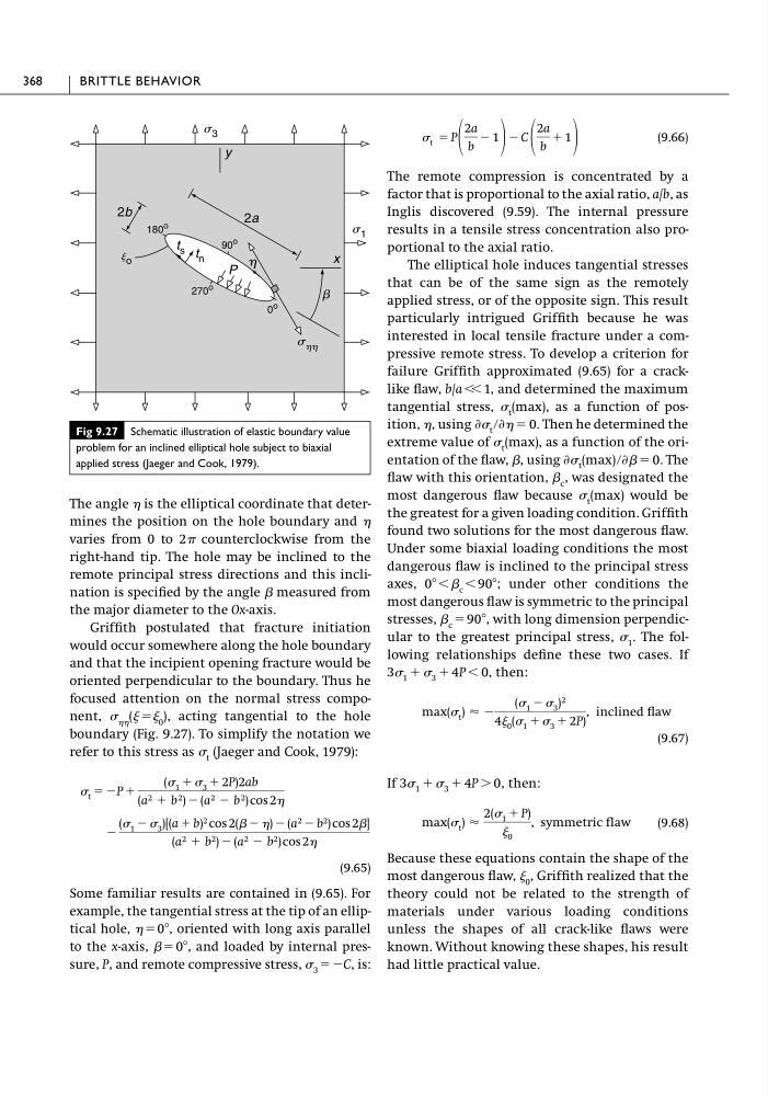
The angle is the elliptical coordinate that determines the position on the hole boundary and
varies from 0 to 2 counterclockwise from the
right-hand tip. The hole may be inclined to the
remote principal stress directions and this inclination is specified by the angle  measured from
the major diameter to the Ox-axis.
Griffith postulated that fracture initiation
would occur somewhere along the hole boundary
and that the incipient opening fracture would be
oriented perpendicular to the boundary. Thus he
focused attention on the normal stress component, (ϭ 0 ), acting tangential to the hole
boundary (Fig. 9.27). To simplify the notation we
refer to this stress as t (Jaeger and Cook, 1979):
(9.65)
Some familiar results are contained in (9.65). For
example, the tangential stress at the tip of an elliptical hole, ϭ 0Њ, oriented with long axis parallel
to the x-axis,  ϭ 0Њ, and loaded by internal pressure, P, and remote compressive stress, 3 ϭϪC, is:
Ϫ
( 1 Ϫ 3 )[(a ϩ b) 2 cos 2( Ϫ ) Ϫ (a 2 Ϫ b 2 ) cos 2]
(a 2 ϩ b 2 ) Ϫ (a 2 Ϫ b 2 ) cos 2
t ϭ ϪP ϩ
( 1 ϩ 3 ϩ 2P)2ab
(a 2 ϩ b 2 ) Ϫ (a 2 Ϫ b 2 ) cos 2
(9.66)
The remote compression is concentrated by a
factor that is proportional to the axial ratio, a/b, as
Inglis discovered (9.59). The internal pressure
results in a tensile stress concentration also proportional to the axial ratio.
The elliptical hole induces tangential stresses
that can be of the same sign as the remotely
applied stress, or of the opposite sign. This result
particularly intrigued Griffith because he was
interested in local tensile fracture under a compressive remote stress. To develop a criterion for
failure Griffith approximated (9.65) for a cracklike flaw, b/a Ͻ Ͻ 1, and determined the maximum
tangential stress, t (max), as a function of position, , using
Then he determined the
extreme value of t (max), as a function of the orientation of the flaw, , using
The
flaw with this orientation,  c , was designated the
most dangerous flaw because t (max) would be
the greatest for a given loading condition. Griffith
found two solutions for the most dangerous flaw.
Under some biaxial loading conditions the most
dangerous flaw is inclined to the principal stress
axes, 0ЊϽ c Ͻ 90Њ; under other conditions the
most dangerous flaw is symmetric to the principal
stresses,  c ϭ 90Њ, with long dimension perpendicular to the greatest principal stress, 1 . The following relationships define these two cases. If
then:
(9.67)
If
then:
(9.68)
Because these equations contain the shape of the
most dangerous flaw, 0 , Griffith realized that the
theory could not be related to the strength of
materials under various loading conditions
unless the shapes of all crack-like flaws were
known. Without knowing these shapes, his result
had little practical value.
max( t ) Ϸ
2( 1 ϩ P)
0
, symmetric flaw
3 1 ϩ 3 ϩ 4P Ͼ 0,
max( t ) Ϸ Ϫ
( 1 Ϫ 3 ) 2
4 0 ( 1 ϩ 3 ϩ 2P)
, inclined flaw
3 1 ϩ 3 ϩ 4P Ͻ 0,
Ѩ t (max) րѨ ϭ 0.
Ѩ t րѨ ϭ 0.
t ϭ P
2a
b
Ϫ 1
Ϫ C
2a
b
ϩ 1
368
BRITTLE BEHAVIOR
Fig 9.27 Schematic illustration of elastic boundary value
problem for an inclined elliptical hole subject to biaxial
applied stress (Jaeger and Cook, 1979).
y
x
2b
2a
b
h
P
s 3
s 1
180
o
90
o
t s t n
270
o
0
o
s hh
j o
varies from 0 to 2 counterclockwise from the
right-hand tip. The hole may be inclined to the
remote principal stress directions and this inclination is specified by the angle  measured from
the major diameter to the Ox-axis.
Griffith postulated that fracture initiation
would occur somewhere along the hole boundary
and that the incipient opening fracture would be
oriented perpendicular to the boundary. Thus he
focused attention on the normal stress component, (ϭ 0 ), acting tangential to the hole
boundary (Fig. 9.27). To simplify the notation we
refer to this stress as t (Jaeger and Cook, 1979):
(9.65)
Some familiar results are contained in (9.65). For
example, the tangential stress at the tip of an elliptical hole, ϭ 0Њ, oriented with long axis parallel
to the x-axis,  ϭ 0Њ, and loaded by internal pressure, P, and remote compressive stress, 3 ϭϪC, is:
Ϫ
( 1 Ϫ 3 )[(a ϩ b) 2 cos 2( Ϫ ) Ϫ (a 2 Ϫ b 2 ) cos 2]
(a 2 ϩ b 2 ) Ϫ (a 2 Ϫ b 2 ) cos 2
t ϭ ϪP ϩ
( 1 ϩ 3 ϩ 2P)2ab
(a 2 ϩ b 2 ) Ϫ (a 2 Ϫ b 2 ) cos 2
(9.66)
The remote compression is concentrated by a
factor that is proportional to the axial ratio, a/b, as
Inglis discovered (9.59). The internal pressure
results in a tensile stress concentration also proportional to the axial ratio.
The elliptical hole induces tangential stresses
that can be of the same sign as the remotely
applied stress, or of the opposite sign. This result
particularly intrigued Griffith because he was
interested in local tensile fracture under a compressive remote stress. To develop a criterion for
failure Griffith approximated (9.65) for a cracklike flaw, b/a Ͻ Ͻ 1, and determined the maximum
tangential stress, t (max), as a function of position, , using
Then he determined the
extreme value of t (max), as a function of the orientation of the flaw, , using
The
flaw with this orientation,  c , was designated the
most dangerous flaw because t (max) would be
the greatest for a given loading condition. Griffith
found two solutions for the most dangerous flaw.
Under some biaxial loading conditions the most
dangerous flaw is inclined to the principal stress
axes, 0ЊϽ c Ͻ 90Њ; under other conditions the
most dangerous flaw is symmetric to the principal
stresses,  c ϭ 90Њ, with long dimension perpendicular to the greatest principal stress, 1 . The following relationships define these two cases. If
then:
(9.67)
If
then:
(9.68)
Because these equations contain the shape of the
most dangerous flaw, 0 , Griffith realized that the
theory could not be related to the strength of
materials under various loading conditions
unless the shapes of all crack-like flaws were
known. Without knowing these shapes, his result
had little practical value.
max( t ) Ϸ
2( 1 ϩ P)
0
, symmetric flaw
3 1 ϩ 3 ϩ 4P Ͼ 0,
max( t ) Ϸ Ϫ
( 1 Ϫ 3 ) 2
4 0 ( 1 ϩ 3 ϩ 2P)
, inclined flaw
3 1 ϩ 3 ϩ 4P Ͻ 0,
Ѩ t (max) րѨ ϭ 0.
Ѩ t րѨ ϭ 0.
t ϭ P
2a
b
Ϫ 1
Ϫ C
2a
b
ϩ 1
368
BRITTLE BEHAVIOR
Fig 9.27 Schematic illustration of elastic boundary value
problem for an inclined elliptical hole subject to biaxial
applied stress (Jaeger and Cook, 1979).
y
x
2b
2a
b
h
P
s 3
s 1
180
o
90
o
t s t n
270
o
0
o
s hh
j o