

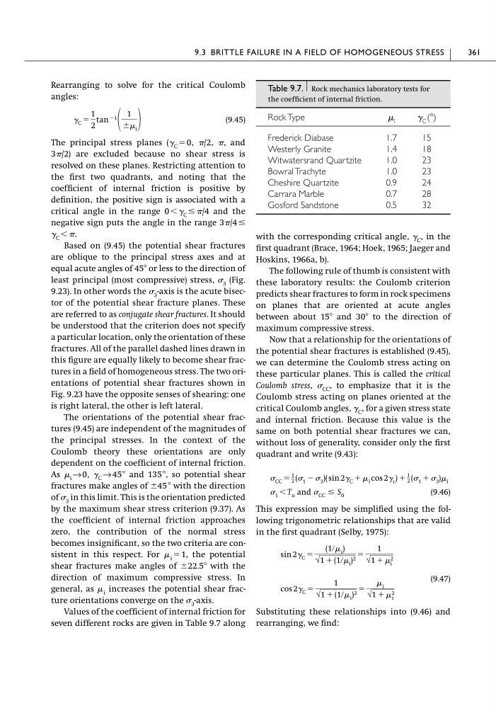
Rearranging to solve for the critical Coulomb
angles:
(9.45)
The principal stress planes (␥ C ϭ 0, /2, , and
3/2) are excluded because no shear stress is
resolved on these planes. Restricting attention to
the first two quadrants, and noting that the
coefficient of internal friction is positive by
definition, the positive sign is associated with a
critical angle in the range 0 Ͻ ␥ C Յ /4 and the
negative sign puts the angle in the range 3/4 Յ
␥ C Ͻ .
Based on (9.45) the potential shear fractures
are oblique to the principal stress axes and at
equal acute angles of 45Њ or less to the direction of
least principal (most compressive) stress, 3 (Fig.
9.23). In other words the 3 -axis is the acute bisector of the potential shear fracture planes. These
are referred to as conjugate shear fractures. It should
be understood that the criterion does not specify
a particular location, only the orientation of these
fractures. All of the parallel dashed lines drawn in
this figure are equally likely to become shear fractures in a field of homogeneous stress. The two orientations of potential shear fractures shown in
Fig. 9.23 have the opposite senses of shearing: one
is right lateral, the other is left lateral.
The orientations of the potential shear fractures (9.45) are independent of the magnitudes of
the principal stresses. In the context of the
Coulomb theory these orientations are only
dependent on the coefficient of internal friction.
As i → 0, ␥ C → 45Њ and 135 Њ, so potential shear
fractures make angles of Ϯ45 Њ with the direction
of 3 in this limit. This is the orientation predicted
by the maximum shear stress criterion (9.37). As
the coefficient of internal friction approaches
zero, the contribution of the normal stress
becomes insignificant, so the two criteria are consistent in this respect. For i ϭ 1, the potential
shear fractures make angles of Ϯ22.5Њ with the
direction of maximum compressive stress. In
general, as i increases the potential shear fracture orientations converge on the 3 -axis.
Values of the coefficient of internal friction for
seven different rocks are given in Table 9.7 along
␥ C ϭ
1
2
tan Ϫ1
1
Ϯ i
with the corresponding critical angle, ␥ C , in the
first quadrant (Brace, 1964; Hoek, 1965; Jaeger and
Hoskins, 1966a, b).
The following rule of thumb is consistent with
these laboratory results: the Coulomb criterion
predicts shear fractures to form in rock specimens
on planes that are oriented at acute angles
between about 15Њ and 30Њ to the direction of
maximum compressive stress.
Now that a relationship for the orientations of
the potential shear fractures is established (9.45),
we can determine the Coulomb stress acting on
these particular planes. This is called the critical
Coulomb stress, CC , to emphasize that it is the
Coulomb stress acting on planes oriented at the
critical Coulomb angles, ␥ C , for a given stress state
and internal friction. Because this value is the
same on both potential shear fractures we can,
without loss of generality, consider only the first
quadrant and write (9.43):
(9.46)
This expression may be simplified using the following trigonometric relationships that are valid
in the first quadrant (Selby, 1975):
(9.47)
Substituting these relationships into (9.46) and
rearranging, we find:
cos 2␥ C ϭ
1
√1 ϩ (1ր i ) 2 ϭ
i
√1 ϩ 2
i
sin 2␥ C ϭ
(1ր i )
√1 ϩ (1ր i ) 2 ϭ
1
√1 ϩ 2
i
1 Ͻ T u and CC Յ S 0
CC ϭ
1
2 ( 1 Ϫ 3 )( sin 2␥ C ϩ i cos 2␥ c ) ϩ
1
2 ( 1 ϩ 3 ) i
9.3 BRITTLE FAILURE IN A FIELD OF HOMOGENEOUS STRESS
361
Table 9.7. Rock mechanics laboratory tests for
the coefficient of internal friction.
Rock Type
i
␥ C (Њ)
Frederick Diabase
1.7
15
Westerly Granite
1.4
18
Witwatersrand Quartzite
1.0
23
Bowral Trachyte
1.0
23
Cheshire Quartzite
0.9
24
Carrara Marble
0.7
28
Gosford Sandstone
0.5
32
angles:
(9.45)
The principal stress planes (␥ C ϭ 0, /2, , and
3/2) are excluded because no shear stress is
resolved on these planes. Restricting attention to
the first two quadrants, and noting that the
coefficient of internal friction is positive by
definition, the positive sign is associated with a
critical angle in the range 0 Ͻ ␥ C Յ /4 and the
negative sign puts the angle in the range 3/4 Յ
␥ C Ͻ .
Based on (9.45) the potential shear fractures
are oblique to the principal stress axes and at
equal acute angles of 45Њ or less to the direction of
least principal (most compressive) stress, 3 (Fig.
9.23). In other words the 3 -axis is the acute bisector of the potential shear fracture planes. These
are referred to as conjugate shear fractures. It should
be understood that the criterion does not specify
a particular location, only the orientation of these
fractures. All of the parallel dashed lines drawn in
this figure are equally likely to become shear fractures in a field of homogeneous stress. The two orientations of potential shear fractures shown in
Fig. 9.23 have the opposite senses of shearing: one
is right lateral, the other is left lateral.
The orientations of the potential shear fractures (9.45) are independent of the magnitudes of
the principal stresses. In the context of the
Coulomb theory these orientations are only
dependent on the coefficient of internal friction.
As i → 0, ␥ C → 45Њ and 135 Њ, so potential shear
fractures make angles of Ϯ45 Њ with the direction
of 3 in this limit. This is the orientation predicted
by the maximum shear stress criterion (9.37). As
the coefficient of internal friction approaches
zero, the contribution of the normal stress
becomes insignificant, so the two criteria are consistent in this respect. For i ϭ 1, the potential
shear fractures make angles of Ϯ22.5Њ with the
direction of maximum compressive stress. In
general, as i increases the potential shear fracture orientations converge on the 3 -axis.
Values of the coefficient of internal friction for
seven different rocks are given in Table 9.7 along
␥ C ϭ
1
2
tan Ϫ1
1
Ϯ i
with the corresponding critical angle, ␥ C , in the
first quadrant (Brace, 1964; Hoek, 1965; Jaeger and
Hoskins, 1966a, b).
The following rule of thumb is consistent with
these laboratory results: the Coulomb criterion
predicts shear fractures to form in rock specimens
on planes that are oriented at acute angles
between about 15Њ and 30Њ to the direction of
maximum compressive stress.
Now that a relationship for the orientations of
the potential shear fractures is established (9.45),
we can determine the Coulomb stress acting on
these particular planes. This is called the critical
Coulomb stress, CC , to emphasize that it is the
Coulomb stress acting on planes oriented at the
critical Coulomb angles, ␥ C , for a given stress state
and internal friction. Because this value is the
same on both potential shear fractures we can,
without loss of generality, consider only the first
quadrant and write (9.43):
(9.46)
This expression may be simplified using the following trigonometric relationships that are valid
in the first quadrant (Selby, 1975):
(9.47)
Substituting these relationships into (9.46) and
rearranging, we find:
cos 2␥ C ϭ
1
√1 ϩ (1ր i ) 2 ϭ
i
√1 ϩ 2
i
sin 2␥ C ϭ
(1ր i )
√1 ϩ (1ր i ) 2 ϭ
1
√1 ϩ 2
i
1 Ͻ T u and CC Յ S 0
CC ϭ
1
2 ( 1 Ϫ 3 )( sin 2␥ C ϩ i cos 2␥ c ) ϩ
1
2 ( 1 ϩ 3 ) i
9.3 BRITTLE FAILURE IN A FIELD OF HOMOGENEOUS STRESS
361
Table 9.7. Rock mechanics laboratory tests for
the coefficient of internal friction.
Rock Type
i
␥ C (Њ)
Frederick Diabase
1.7
15
Westerly Granite
1.4
18
Witwatersrand Quartzite
1.0
23
Bowral Trachyte
1.0
23
Cheshire Quartzite
0.9
24
Carrara Marble
0.7
28
Gosford Sandstone
0.5
32