

The answer comes from the engineering discipline called fracture mechanics (Rice, 1968; Lawn
and Wilshaw, 1975; Kanninen and Popelar, 1985;
Anderson, 1995). By fracture propagation we mean
that two new surfaces develop along an extension
of the fracture plane that merge with and become
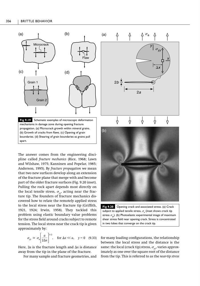
part of the older fracture surfaces (Fig. 9.20 inset).
Pulling the rock apart depends most directly on
the local tensile stress, yy , acting near the fracture tip. The founders of fracture mechanics discovered how to relate the remotely applied stress
to the local stress near the fracture tip (Griffith,
1921, 1924; Irwin, 1958). They tackled this
problem using elastic boundary value problems
for the stress field around cracks subject to remote
tension. The local stress near the crack tip is given
approximately by:
(9.33)
Here, 2a is the fracture length and ⌬x is distance
away from the tip in the plane of the fracture.
For many sample and fracture geometries, and
yy Х a ΄
a
2⌬x ΅
1ր2
, for ⌬x Ͻ Ͻ a, y ϭ 0
for many loading configurations, the relationship
between the local stress and the distance is the
same: the local (crack tip) stress, yy , varies approximately as one over the square root of the distance
from the tip. This is referred to as the near-tip stress
356
BRITTLE BEHAVIOR
Fig 9.19 Schematic examples of microscopic deformation
mechanisms in damage zone during opening fracture
propagation. (a) Microcrack growth within mineral grains.
(b) Growth of cracks from flaws. (c) Opening of grain
boundaries. (d) Shearing of grain boundaries as grains pull
apart.
Microcrack
(a)
(b)
(d)
(c)
Flaw
Grain 1
Grain 2
Fig 9.20 Opening crack and associated stress. (a) Crack
subject to applied tensile stress, a (inset shows crack tip
stress yy ). (b) Photoelastic experimental image of maximum
shear stress field near opening crack. Stress is concentrated
in two lobes that converge on the crack tip.
2b
2a
s a
y
x
⌬x
s yy
(a)
(b)
and Wilshaw, 1975; Kanninen and Popelar, 1985;
Anderson, 1995). By fracture propagation we mean
that two new surfaces develop along an extension
of the fracture plane that merge with and become
part of the older fracture surfaces (Fig. 9.20 inset).
Pulling the rock apart depends most directly on
the local tensile stress, yy , acting near the fracture tip. The founders of fracture mechanics discovered how to relate the remotely applied stress
to the local stress near the fracture tip (Griffith,
1921, 1924; Irwin, 1958). They tackled this
problem using elastic boundary value problems
for the stress field around cracks subject to remote
tension. The local stress near the crack tip is given
approximately by:
(9.33)
Here, 2a is the fracture length and ⌬x is distance
away from the tip in the plane of the fracture.
For many sample and fracture geometries, and
yy Х a ΄
a
2⌬x ΅
1ր2
, for ⌬x Ͻ Ͻ a, y ϭ 0
for many loading configurations, the relationship
between the local stress and the distance is the
same: the local (crack tip) stress, yy , varies approximately as one over the square root of the distance
from the tip. This is referred to as the near-tip stress
356
BRITTLE BEHAVIOR
Fig 9.19 Schematic examples of microscopic deformation
mechanisms in damage zone during opening fracture
propagation. (a) Microcrack growth within mineral grains.
(b) Growth of cracks from flaws. (c) Opening of grain
boundaries. (d) Shearing of grain boundaries as grains pull
apart.
Microcrack
(a)
(b)
(d)
(c)
Flaw
Grain 1
Grain 2
Fig 9.20 Opening crack and associated stress. (a) Crack
subject to applied tensile stress, a (inset shows crack tip
stress yy ). (b) Photoelastic experimental image of maximum
shear stress field near opening crack. Stress is concentrated
in two lobes that converge on the crack tip.
2b
2a
s a
y
x
⌬x
s yy
(a)
(b)