

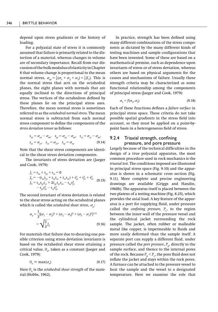
depend upon stress gradients or the history of
loading.
For a polyaxial state of stress it is commonly
assumed that failure is primarily related to the distortion of a material, whereas changes in volume
are of secondary importance. Recall from our discussion of the bulk modulus of elasticity in Chapter
8 that volume change is proportional to the mean
normal stress,
This is
the normal stress that acts on the octahedral
planes, the eight planes with normals that are
equally inclined to the directions of principal
stress. The vertices of the octahedron defined by
these planes lie on the principal stress axes.
Therefore, the mean normal stress is sometimes
referred to as the octahedral normal stress. The mean
normal stress is subtracted from each normal
stress component to define the components of the
stress deviation tensor as follows:
(9.14)
Note that the shear stress components are identical to the shear stress deviation components.
The invariants of stress deviation are (Jaeger
and Cook, 1979):
(9.15)
The second invariant of stress deviation is related
to the shear stress acting on the octahedral planes
which is called the octahedral shear stress, o :
(9.16)
For materials that failure due to shearing one possible criterion using stress deviation invariants is
based on the octahedral shear stress attaining a
critical value, O o , taken as a constant (Jaeger and
Cook, 1979):
(9.17)
Here O o is the octahedral shear strength of the material (Hobbs, 1962).
O o ϵ max ( o )
ϭ
√
2
3
J 2
o ϭ
1
3
[( 1 Ϫ 2 ) 2 ϩ ( 2 Ϫ 3 ) 2 ϩ ( 3 Ϫ 1 ) 2 ] 1ր2
Ϫ s yy s 2
zx Ϫ s zz s 2
xy
J 3 ϭ s xx s yy s zz ϩ 2s xy s yz s zx Ϫ s xx s 2
yz
J 2 ϭ Ϫ(s xx s yy ϩ s yy s zz ϩ s zz s xx ) ϩ s 2
xy ϩ s 2
yz ϩ s 2
zx
J 1 ϭ s xx ϩ s yy ϩ s zz ϭ 0
s yz ϭ yz , s zx ϭ zx , s xy ϭ xy
s xx ϭ xx Ϫ m , s yy ϭ yy Ϫ m , s zz ϭ zz Ϫ m ,
m ϭ
1
3 ( 1 ϩ 2 ϩ 3 ) ϭ
1
3 (I 1 ).
In practice, strength has been defined using
many different combinations of the stress components as dictated by the many different kinds of
testing machines and sample configurations that
have been invented. Some of these are based on a
mathematical premise, such as dependence upon
invariants of stress or of stress deviation, whereas
others are based on physical arguments for the
causes and mechanisms of failure. Usually these
strength criteria may be characterized as some
functional relationship among the components
of principal stress (Jaeger and Cook, 1979):
(9.18)
Each of these functions defines a failure surface in
principal stress space. These criteria do not take
possible spatial gradients in the stress field into
account, so they must be applied on a point-bypoint basis in a heterogeneous field of stress.
9.2.4 Triaxial strength, confining
pressure, and pore pressure
Largely because of the technical difficulties in the
design of a true polyaxial apparatus, the most
common procedure used in rock mechanics is the
triaxial test. The conditions imposed are illustrated
in principal stress space (Fig. 9.10) and the apparatus is shown in a schematic cross section (Fig.
9.11). More complete and precise engineering
drawings are available (Griggs and Handin,
1960b). The apparatus itself is placed between the
two platens of a testing machine (Fig. 8.25), which
provides the axial load. A key feature of the apparatus is a port for supplying fluid, under pressure
called the confining pressure, P c , to the region
between the inner wall of the pressure vessel and
the cylindrical jacket surrounding the rock
sample. The jacket, often rubber or malleable
metal like copper, is impermeable to fluids and
more easily deformed than the sample itself. A
separate port can supply a different fluid, under
pressure called the pore pressure, P p , directly to the
sample surface, and thence to the internal pores
of the rock. Because P p Ͻ P c , the pore fluid does not
inflate the jacket and stays within the rock pores.
A furnace can be attached to the pressure vessel to
heat the sample and the vessel to a designated
temperature. Here we examine the role that
1 ϭ f ( 2 , 3 )
346
BRITTLE BEHAVIOR
loading.
For a polyaxial state of stress it is commonly
assumed that failure is primarily related to the distortion of a material, whereas changes in volume
are of secondary importance. Recall from our discussion of the bulk modulus of elasticity in Chapter
8 that volume change is proportional to the mean
normal stress,
This is
the normal stress that acts on the octahedral
planes, the eight planes with normals that are
equally inclined to the directions of principal
stress. The vertices of the octahedron defined by
these planes lie on the principal stress axes.
Therefore, the mean normal stress is sometimes
referred to as the octahedral normal stress. The mean
normal stress is subtracted from each normal
stress component to define the components of the
stress deviation tensor as follows:
(9.14)
Note that the shear stress components are identical to the shear stress deviation components.
The invariants of stress deviation are (Jaeger
and Cook, 1979):
(9.15)
The second invariant of stress deviation is related
to the shear stress acting on the octahedral planes
which is called the octahedral shear stress, o :
(9.16)
For materials that failure due to shearing one possible criterion using stress deviation invariants is
based on the octahedral shear stress attaining a
critical value, O o , taken as a constant (Jaeger and
Cook, 1979):
(9.17)
Here O o is the octahedral shear strength of the material (Hobbs, 1962).
O o ϵ max ( o )
ϭ
√
2
3
J 2
o ϭ
1
3
[( 1 Ϫ 2 ) 2 ϩ ( 2 Ϫ 3 ) 2 ϩ ( 3 Ϫ 1 ) 2 ] 1ր2
Ϫ s yy s 2
zx Ϫ s zz s 2
xy
J 3 ϭ s xx s yy s zz ϩ 2s xy s yz s zx Ϫ s xx s 2
yz
J 2 ϭ Ϫ(s xx s yy ϩ s yy s zz ϩ s zz s xx ) ϩ s 2
xy ϩ s 2
yz ϩ s 2
zx
J 1 ϭ s xx ϩ s yy ϩ s zz ϭ 0
s yz ϭ yz , s zx ϭ zx , s xy ϭ xy
s xx ϭ xx Ϫ m , s yy ϭ yy Ϫ m , s zz ϭ zz Ϫ m ,
m ϭ
1
3 ( 1 ϩ 2 ϩ 3 ) ϭ
1
3 (I 1 ).
In practice, strength has been defined using
many different combinations of the stress components as dictated by the many different kinds of
testing machines and sample configurations that
have been invented. Some of these are based on a
mathematical premise, such as dependence upon
invariants of stress or of stress deviation, whereas
others are based on physical arguments for the
causes and mechanisms of failure. Usually these
strength criteria may be characterized as some
functional relationship among the components
of principal stress (Jaeger and Cook, 1979):
(9.18)
Each of these functions defines a failure surface in
principal stress space. These criteria do not take
possible spatial gradients in the stress field into
account, so they must be applied on a point-bypoint basis in a heterogeneous field of stress.
9.2.4 Triaxial strength, confining
pressure, and pore pressure
Largely because of the technical difficulties in the
design of a true polyaxial apparatus, the most
common procedure used in rock mechanics is the
triaxial test. The conditions imposed are illustrated
in principal stress space (Fig. 9.10) and the apparatus is shown in a schematic cross section (Fig.
9.11). More complete and precise engineering
drawings are available (Griggs and Handin,
1960b). The apparatus itself is placed between the
two platens of a testing machine (Fig. 8.25), which
provides the axial load. A key feature of the apparatus is a port for supplying fluid, under pressure
called the confining pressure, P c , to the region
between the inner wall of the pressure vessel and
the cylindrical jacket surrounding the rock
sample. The jacket, often rubber or malleable
metal like copper, is impermeable to fluids and
more easily deformed than the sample itself. A
separate port can supply a different fluid, under
pressure called the pore pressure, P p , directly to the
sample surface, and thence to the internal pores
of the rock. Because P p Ͻ P c , the pore fluid does not
inflate the jacket and stays within the rock pores.
A furnace can be attached to the pressure vessel to
heat the sample and the vessel to a designated
temperature. Here we examine the role that
1 ϭ f ( 2 , 3 )
346
BRITTLE BEHAVIOR