

strata, would find it easier to spread laterally at
shallower depths, because there is less overburden. If this conjecture were correct, one would
expect to find laccoliths with lesser diameters
exposed lower in the stratigraphic sequence. On
the other hand one might imagine that magma
would have to spread farther at greater depth to
gain the leverage necessary to push the overburden upward. If this conjecture were correct, one
would expect to find laccoliths with greater diameters exposed lower in the stratigraphic sequence.
Both conjectures cannot be correct.
To evaluate these conjectures and thereby
clarify the mechanics of laccolith formation
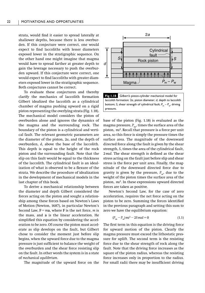
Gilbert idealized the laccolith as a cylindrical
chamber of magma pushing upward on a rigid
piston representing the overlying strata (Fig. 1.18).
The mechanical model considers the piston of
overburden alone and ignores the dynamics of
the magma and the surrounding rock. The
boundary of the piston is a cylindrical and vertical fault. The relevant geometric parameters are
the diameter of the piston, 2a, and the depth of
overburden, d, above the base of the laccolith.
This depth is equal to the height of the rock
piston and the surrounding fault. Note that the
slip on this fault would be equal to the thickness
of the laccolith. The cylindrical fault is an idealization of what is observed to be a flexure of the
strata. We describe the procedure of idealization
in the development of mechanical models in the
last chapter of this book.
To derive a mechanical relationship between
the diameter and depth Gilbert considered the
forces acting on the piston and sought a relationship among these forces based on Newton’s Laws
of Motion (Newton, 1687), in particular Newton’s
Second Law, F ϭ ma, where F is the net force, m is
the mass, and a is the linear acceleration. He
simplified this equation by considering the acceleration to be zero. Of course the piston must accelerate as slip develops on the fault, but Gilbert
chose to consider the moment just before slip
begins, when the upward force due to the magma
pressure is just sufficient to balance the weight of
the overburden and the shear force resisting slip
on the fault. In other words the system is in a state
of mechanical equilibrium.
The magnitude of the upward force on the
base of the piston (Fig. 1.18) is evaluated as the
magma pressure, P m , times the surface area of the
piston, a
2 . Recall that pressure is a force per unit
area, so this force is simply the pressure times the
surface area. The magnitude of the downward
directed force along the fault is given by the shear
strength, S, times the area of the cylindrical fault,
2ad. The shear strength is defined as the shear
stress acting on the fault just before slip and shear
stress is the force per unit area. Finally, the magnitude of the downward directed force due to
gravity is given by the pressure, P w , due to the
weight of the piston times the surface area of the
piston, a
2 . In these expressions upward directed
forces are taken as positive.
Newton’s Second Law, for the case of zero
acceleration, requires the net force acting on the
piston to be zero. Summing the forces identified
in the previous paragraph and setting this sum to
zero we have the equilibrium equation:
(P m Ϫ P w )a
2 Ϫ 2Sad ϭ 0
(1.1)
The first term in this equation is the driving force
for upward motion of the piston. Clearly the
magma pressure must exceed the lithostatic pressure for uplift. The second term is the resisting
force due to the shear strength of rock along the
fault. Note that the driving force increases as the
square of the piston radius, whereas the resisting
force increases only in proportion to the radius.
For small radii there may be insufficient driving
22
MOTIVATIONS AND OPPORTUNITIES
2a
d
Cylindrical
fault
Rock piston
S
Magma
P m – P w
S
Fig 1.18 Gilbert’s piston-cylinder mechanical model for
laccolith formation: 2a, piston diameter; d, depth to laccolith
bottom; S, shear strength of cylindrical fault; P m – P w , driving
pressure.
shallower depths, because there is less overburden. If this conjecture were correct, one would
expect to find laccoliths with lesser diameters
exposed lower in the stratigraphic sequence. On
the other hand one might imagine that magma
would have to spread farther at greater depth to
gain the leverage necessary to push the overburden upward. If this conjecture were correct, one
would expect to find laccoliths with greater diameters exposed lower in the stratigraphic sequence.
Both conjectures cannot be correct.
To evaluate these conjectures and thereby
clarify the mechanics of laccolith formation
Gilbert idealized the laccolith as a cylindrical
chamber of magma pushing upward on a rigid
piston representing the overlying strata (Fig. 1.18).
The mechanical model considers the piston of
overburden alone and ignores the dynamics of
the magma and the surrounding rock. The
boundary of the piston is a cylindrical and vertical fault. The relevant geometric parameters are
the diameter of the piston, 2a, and the depth of
overburden, d, above the base of the laccolith.
This depth is equal to the height of the rock
piston and the surrounding fault. Note that the
slip on this fault would be equal to the thickness
of the laccolith. The cylindrical fault is an idealization of what is observed to be a flexure of the
strata. We describe the procedure of idealization
in the development of mechanical models in the
last chapter of this book.
To derive a mechanical relationship between
the diameter and depth Gilbert considered the
forces acting on the piston and sought a relationship among these forces based on Newton’s Laws
of Motion (Newton, 1687), in particular Newton’s
Second Law, F ϭ ma, where F is the net force, m is
the mass, and a is the linear acceleration. He
simplified this equation by considering the acceleration to be zero. Of course the piston must accelerate as slip develops on the fault, but Gilbert
chose to consider the moment just before slip
begins, when the upward force due to the magma
pressure is just sufficient to balance the weight of
the overburden and the shear force resisting slip
on the fault. In other words the system is in a state
of mechanical equilibrium.
The magnitude of the upward force on the
base of the piston (Fig. 1.18) is evaluated as the
magma pressure, P m , times the surface area of the
piston, a
2 . Recall that pressure is a force per unit
area, so this force is simply the pressure times the
surface area. The magnitude of the downward
directed force along the fault is given by the shear
strength, S, times the area of the cylindrical fault,
2ad. The shear strength is defined as the shear
stress acting on the fault just before slip and shear
stress is the force per unit area. Finally, the magnitude of the downward directed force due to
gravity is given by the pressure, P w , due to the
weight of the piston times the surface area of the
piston, a
2 . In these expressions upward directed
forces are taken as positive.
Newton’s Second Law, for the case of zero
acceleration, requires the net force acting on the
piston to be zero. Summing the forces identified
in the previous paragraph and setting this sum to
zero we have the equilibrium equation:
(P m Ϫ P w )a
2 Ϫ 2Sad ϭ 0
(1.1)
The first term in this equation is the driving force
for upward motion of the piston. Clearly the
magma pressure must exceed the lithostatic pressure for uplift. The second term is the resisting
force due to the shear strength of rock along the
fault. Note that the driving force increases as the
square of the piston radius, whereas the resisting
force increases only in proportion to the radius.
For small radii there may be insufficient driving
22
MOTIVATIONS AND OPPORTUNITIES
2a
d
Cylindrical
fault
Rock piston
S
Magma
P m – P w
S
Fig 1.18 Gilbert’s piston-cylinder mechanical model for
laccolith formation: 2a, piston diameter; d, depth to laccolith
bottom; S, shear strength of cylindrical fault; P m – P w , driving
pressure.