

The minimum value of the axial strain (contraction) before failure is determined by comparing the Young’s moduli and uniaxial compressive
strengths taken from Tables 8.2 and 9.2, respectively. Using 1 : 300 as a representative value for
the ratio of compressive strength to Young’s
modulus, we have
This and the preceding example should reinforce
the important concept that stiffness and strength
are different by three or four orders of magnitude,
and that the magnitudes of the axial strains at the
initiation of failure for these brittle materials are
on the order of 10
Ϫ3 to 10
Ϫ4 .
Given the very small elastic strains that
precede failure in uniaxial tests one might conclude that elastic deformation is unimportant for
structural geologists. This would be a mistake. For
one thing, it is common to have a “sample”
length, L, measured in kilometers for structures
in the Earth, so typical displacements would be on
the order of decimeters to meters. For example,
the dike at Ship Rock (Fig. 2.7) is about 3 km long
and the adjacent rock was displaced about 1 m as
the dike opened. Some of the fault segments that
ruptured during the Hector Mine earthquake (Fig.
8.13) are more than 10 km long and slip up to
several meters was recorded along their surface
traces. Yet the surface displacement field clearly
correlates with that of an elastic model. Thus, for
structural geologists, the elastic strains that
accompany brittle fracture play an important role
in crustal deformation.
The most prominent macroscopic mechanism
that acts to limit the stress under conditions of
uniaxial testing is fracture. The word macroscopic is
used here to refer to phenomena, observable with
the unaided eye, such as extension fractures, splitting fractures, and shear fractures (Figs. 9.1 and
9.2). In contrast, the word microscopic refers to the
grain-scale phenomena within the sample that
individually are visible only with a microscope or
hand lens. The details of the grain-scale deformation during these experiments, the ways in which
this deformation proceeds to weaken the whole
specimen over the course of the test, and the strain
localization into discrete fractures along which the
specimen breaks can be quite complex (Peng and
Johnson, 1972). A great deal of research has been
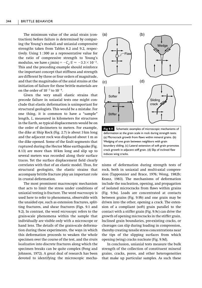
devoted to identifying the microscopic mechae a (min) ϭ ϪC u րE Ϸ Ϫ3.3 ϫ 10 Ϫ3 .
nisms of deformation during strength tests of
rock, both in uniaxial and multi-axial compression (Tapponnier and Brace, 1976; Wong, 1982b;
Kranz, 1983). The mechanisms of deformation
include the nucleation, opening, and propagation
of isolated microcracks from flaws within grains
(Fig. 9.9a). Loads are concentrated at contacts
between grains (Fig. 9.9b) and one grain may be
driven into the other, opening a crack. The extension of a compliant (soft) grain parallel to the
contact with a stiffer grain (Fig. 9.9c) can drive the
growth of opening microcracks in the stiffer grain.
Inclined grain boundaries, pre-existing cracks, or
cleavages can slip during loading in compression,
thereby creating tensile stress concentrations near
the tips of the slipping surfaces from which
opening (wing) cracks nucleate (Fig. 9.9d).
In conclusion, uniaxial tests measure the bulk
strength of the collection of constituent mineral
grains, cracks, pores, and other heterogeneities
that make up particular samples. As such these
344
BRITTLE BEHAVIOR
Fig 9.9 Schematic examples of microscopic mechanisms of
deformation at the grain scale in rock during strength tests.
(a) Microcrack growth from flaws within mineral grains. (b)
Wedging of one grain between neighbors with grain
boundary sliding. (c) Lateral extension of soft grain promotes
crack growth in adjacent stiff grain. (d) Slip of inclined flaw
induces wing cracks.
(a)
(b)
(c)
Flaw
(d)
Softer
Stiffer
Wedge
Sliding
crack
strengths taken from Tables 8.2 and 9.2, respectively. Using 1 : 300 as a representative value for
the ratio of compressive strength to Young’s
modulus, we have
This and the preceding example should reinforce
the important concept that stiffness and strength
are different by three or four orders of magnitude,
and that the magnitudes of the axial strains at the
initiation of failure for these brittle materials are
on the order of 10
Ϫ3 to 10
Ϫ4 .
Given the very small elastic strains that
precede failure in uniaxial tests one might conclude that elastic deformation is unimportant for
structural geologists. This would be a mistake. For
one thing, it is common to have a “sample”
length, L, measured in kilometers for structures
in the Earth, so typical displacements would be on
the order of decimeters to meters. For example,
the dike at Ship Rock (Fig. 2.7) is about 3 km long
and the adjacent rock was displaced about 1 m as
the dike opened. Some of the fault segments that
ruptured during the Hector Mine earthquake (Fig.
8.13) are more than 10 km long and slip up to
several meters was recorded along their surface
traces. Yet the surface displacement field clearly
correlates with that of an elastic model. Thus, for
structural geologists, the elastic strains that
accompany brittle fracture play an important role
in crustal deformation.
The most prominent macroscopic mechanism
that acts to limit the stress under conditions of
uniaxial testing is fracture. The word macroscopic is
used here to refer to phenomena, observable with
the unaided eye, such as extension fractures, splitting fractures, and shear fractures (Figs. 9.1 and
9.2). In contrast, the word microscopic refers to the
grain-scale phenomena within the sample that
individually are visible only with a microscope or
hand lens. The details of the grain-scale deformation during these experiments, the ways in which
this deformation proceeds to weaken the whole
specimen over the course of the test, and the strain
localization into discrete fractures along which the
specimen breaks can be quite complex (Peng and
Johnson, 1972). A great deal of research has been
devoted to identifying the microscopic mechae a (min) ϭ ϪC u րE Ϸ Ϫ3.3 ϫ 10 Ϫ3 .
nisms of deformation during strength tests of
rock, both in uniaxial and multi-axial compression (Tapponnier and Brace, 1976; Wong, 1982b;
Kranz, 1983). The mechanisms of deformation
include the nucleation, opening, and propagation
of isolated microcracks from flaws within grains
(Fig. 9.9a). Loads are concentrated at contacts
between grains (Fig. 9.9b) and one grain may be
driven into the other, opening a crack. The extension of a compliant (soft) grain parallel to the
contact with a stiffer grain (Fig. 9.9c) can drive the
growth of opening microcracks in the stiffer grain.
Inclined grain boundaries, pre-existing cracks, or
cleavages can slip during loading in compression,
thereby creating tensile stress concentrations near
the tips of the slipping surfaces from which
opening (wing) cracks nucleate (Fig. 9.9d).
In conclusion, uniaxial tests measure the bulk
strength of the collection of constituent mineral
grains, cracks, pores, and other heterogeneities
that make up particular samples. As such these
344
BRITTLE BEHAVIOR
Fig 9.9 Schematic examples of microscopic mechanisms of
deformation at the grain scale in rock during strength tests.
(a) Microcrack growth from flaws within mineral grains. (b)
Wedging of one grain between neighbors with grain
boundary sliding. (c) Lateral extension of soft grain promotes
crack growth in adjacent stiff grain. (d) Slip of inclined flaw
induces wing cracks.
(a)
(b)
(c)
Flaw
(d)
Softer
Stiffer
Wedge
Sliding
crack