

To account for the stress perturbation of the
valley, the first term in the third line of (8.85) is
taken with the constant c 1 ���g*R
2 , so the Airy
stress function is:
(8.89)
The polar stress components are found using
(8.75)–(8.77):
(8.90)
Everywhere on the circular boundary, r � R, the
perturbing radial stress is just sufficient to reduce
the gravitational radial stress to zero. Both the
gravitation and perturbing shear stress are zero.
Therefore the boundary conditions on the valley
wall are satisfied. Because the sin� terms are zero
on the horizontal segments of the boundary, it is
traction free. Because the perturbing stress scales
with (R
2 /r), its contribution goes toward zero for
radial distances that are large compared to the
valley radius and the stress state approaches that
due to gravity alone (8.88).
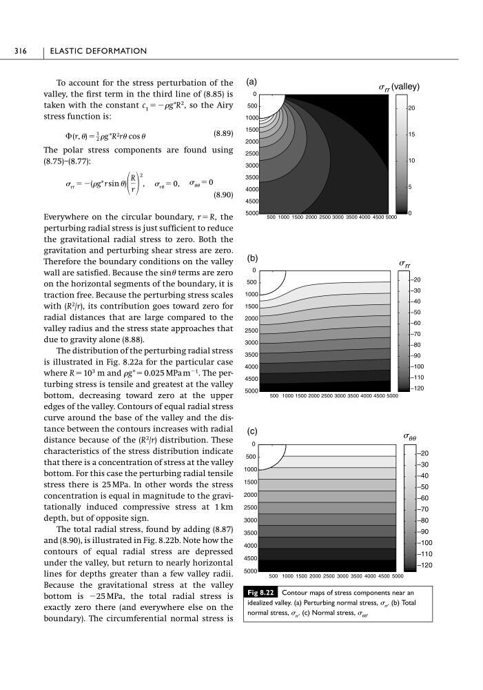
The distribution of the perturbing radial stress
is illustrated in Fig. 8.22a for the particular case
where R � 10
3 m and �g* � 0.025 MPa m
�1 . The perturbing stress is tensile and greatest at the valley
bottom, decreasing toward zero at the upper
edges of the valley. Contours of equal radial stress
curve around the base of the valley and the distance between the contours increases with radial
distance because of the (R
2 /r) distribution. These
characteristics of the stress distribution indicate
that there is a concentration of stress at the valley
bottom. For this case the perturbing radial tensile
stress there is 25 MPa. In other words the stress
concentration is equal in magnitude to the gravitationally induced compressive stress at 1 km
depth, but of opposite sign.
The total radial stress, found by adding (8.87)
and (8.90), is illustrated in Fig. 8.22b. Note how the
contours of equal radial stress are depressed
under the valley, but return to nearly horizontal
lines for depths greater than a few valley radii.
Because the gravitational stress at the valley
bottom is �25 MPa, the total radial stress is
exactly zero there (and everywhere else on the
boundary). The circumferential normal stress is
� �� � 0
� rr � �(�g* r sin �)
R
r
2
, � r� � 0,
� (r, �) �
1
2 �g *R 2 r� cos �
316
ELASTIC DEFORMATION
Fig 8.22 Contour maps of stress components near an
idealized valley. (a) Perturbing normal stress, � rr . (b) Total
normal stress, � rr . (c) Normal stress, � �� .
–120
–110
–100
–90
–80
–70
–60
–50
–40
–30
–20
500 1000 1500 2000 2500 3000 3500 4000 4500 5000
5000
4500
4000
3500
3000
2500
2000
1500
1000
500
0
(c)
s uu
0
5
10
15
20
500 1000 1500 2000 2500 3000 3500 4000 4500 5000
5000
4500
4000
3500
3000
2500
2000
1500
1000
500
0
(a)
s rr (valley)
–120
–110
–100
–90
–80
–70
–60
–50
–40
–30
–20
500 1000 1500 2000 2500 3000 3500 4000 4500 5000
5000
4500
4000
3500
3000
2500
2000
1500
1000
500
0
(b)
s rr
valley, the first term in the third line of (8.85) is
taken with the constant c 1 ���g*R
2 , so the Airy
stress function is:
(8.89)
The polar stress components are found using
(8.75)–(8.77):
(8.90)
Everywhere on the circular boundary, r � R, the
perturbing radial stress is just sufficient to reduce
the gravitational radial stress to zero. Both the
gravitation and perturbing shear stress are zero.
Therefore the boundary conditions on the valley
wall are satisfied. Because the sin� terms are zero
on the horizontal segments of the boundary, it is
traction free. Because the perturbing stress scales
with (R
2 /r), its contribution goes toward zero for
radial distances that are large compared to the
valley radius and the stress state approaches that
due to gravity alone (8.88).
The distribution of the perturbing radial stress
is illustrated in Fig. 8.22a for the particular case
where R � 10
3 m and �g* � 0.025 MPa m
�1 . The perturbing stress is tensile and greatest at the valley
bottom, decreasing toward zero at the upper
edges of the valley. Contours of equal radial stress
curve around the base of the valley and the distance between the contours increases with radial
distance because of the (R
2 /r) distribution. These
characteristics of the stress distribution indicate
that there is a concentration of stress at the valley
bottom. For this case the perturbing radial tensile
stress there is 25 MPa. In other words the stress
concentration is equal in magnitude to the gravitationally induced compressive stress at 1 km
depth, but of opposite sign.
The total radial stress, found by adding (8.87)
and (8.90), is illustrated in Fig. 8.22b. Note how the
contours of equal radial stress are depressed
under the valley, but return to nearly horizontal
lines for depths greater than a few valley radii.
Because the gravitational stress at the valley
bottom is �25 MPa, the total radial stress is
exactly zero there (and everywhere else on the
boundary). The circumferential normal stress is
� �� � 0
� rr � �(�g* r sin �)
R
r
2
, � r� � 0,
� (r, �) �
1
2 �g *R 2 r� cos �
316
ELASTIC DEFORMATION
Fig 8.22 Contour maps of stress components near an
idealized valley. (a) Perturbing normal stress, � rr . (b) Total
normal stress, � rr . (c) Normal stress, � �� .
–120
–110
–100
–90
–80
–70
–60
–50
–40
–30
–20
500 1000 1500 2000 2500 3000 3500 4000 4500 5000
5000
4500
4000
3500
3000
2500
2000
1500
1000
500
0
(c)
s uu
0
5
10
15
20
500 1000 1500 2000 2500 3000 3500 4000 4500 5000
5000
4500
4000
3500
3000
2500
2000
1500
1000
500
0
(a)
s rr (valley)
–120
–110
–100
–90
–80
–70
–60
–50
–40
–30
–20
500 1000 1500 2000 2500 3000 3500 4000 4500 5000
5000
4500
4000
3500
3000
2500
2000
1500
1000
500
0
(b)
s rr