

8.4 Quasi-static traction boundary
value problems
In this section we take the equations of equilibrium,
written in terms of the stresses, as the dependent
variables. Constraints on the infinitesimal strain
field that arise from the kinematic relations require
that we incorporate conditions of compatibility,
written in terms of the stress components, into the
set of governing equations. Solving these equations
for the stress components, the strains are calculated
using Hooke’s Law and the displacements are calculated by integration of the kinematic relations.
The Airy stress function is introduced in Cartesian
coordinates and used to solve a complete twodimensional problem for a rectangular region of
Earth’s crust subject to simple tectonic and gravitational loading conditions. The generalized solution
for two-dimensional problems in polar coordinates
is introduced and used to model a cylindrical valley
in an elastic half-space.
8.4.1 The Airy stress function in twodimensional Cartesian coordinates
The six independent stress components (8.19) are
reduced to three for two-dimensional problems
(Timoshenko and Goodier, 1970, p. 15). One class of
such problems, referred to as plane stress, applies to
very thin plates with no tractions applied to either
surface. Plane stress is widely used in engineering
applications, but it has fewer applications in structural geology. Although the crust of the Earth can
be approximated geometrically as a thin plate or
spherical shell in the context of plate tectonics,
only the upper surface is traction free (neglecting
wind shear and atmospheric pressure). Sedimentary strata also can be approximated geometrically as thin plates, but they are bounded on
both sides by layers that impose non-zero tractions. Therefore, the stress conditions in the interior of these thin plates are unlikely to be
approximated by plane stress conditions.
A second class of two-dimensional problems,
called plane strain, was defined in (8.30) and led to
a pair of governing equations, (8.31) and (8.32),
with the two in-plane displacement components
as the dependent variables. Here, in contrast, the
308
ELASTIC DEFORMATION
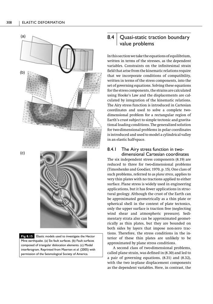
Fig 8.15 Elastic models used to investigate the Hector
Mine earthquake. (a) Six fault surfaces. (b) Fault surfaces
composed of triangular dislocation elements. (c) Model
interferogram. Reprinted from Maerten et al. (2005) with
permission of the Seismological Society of America.
value problems
In this section we take the equations of equilibrium,
written in terms of the stresses, as the dependent
variables. Constraints on the infinitesimal strain
field that arise from the kinematic relations require
that we incorporate conditions of compatibility,
written in terms of the stress components, into the
set of governing equations. Solving these equations
for the stress components, the strains are calculated
using Hooke’s Law and the displacements are calculated by integration of the kinematic relations.
The Airy stress function is introduced in Cartesian
coordinates and used to solve a complete twodimensional problem for a rectangular region of
Earth’s crust subject to simple tectonic and gravitational loading conditions. The generalized solution
for two-dimensional problems in polar coordinates
is introduced and used to model a cylindrical valley
in an elastic half-space.
8.4.1 The Airy stress function in twodimensional Cartesian coordinates
The six independent stress components (8.19) are
reduced to three for two-dimensional problems
(Timoshenko and Goodier, 1970, p. 15). One class of
such problems, referred to as plane stress, applies to
very thin plates with no tractions applied to either
surface. Plane stress is widely used in engineering
applications, but it has fewer applications in structural geology. Although the crust of the Earth can
be approximated geometrically as a thin plate or
spherical shell in the context of plate tectonics,
only the upper surface is traction free (neglecting
wind shear and atmospheric pressure). Sedimentary strata also can be approximated geometrically as thin plates, but they are bounded on
both sides by layers that impose non-zero tractions. Therefore, the stress conditions in the interior of these thin plates are unlikely to be
approximated by plane stress conditions.
A second class of two-dimensional problems,
called plane strain, was defined in (8.30) and led to
a pair of governing equations, (8.31) and (8.32),
with the two in-plane displacement components
as the dependent variables. Here, in contrast, the
308
ELASTIC DEFORMATION
Fig 8.15 Elastic models used to investigate the Hector
Mine earthquake. (a) Six fault surfaces. (b) Fault surfaces
composed of triangular dislocation elements. (c) Model
interferogram. Reprinted from Maerten et al. (2005) with
permission of the Seismological Society of America.