

half-plane of atoms (Fig. 8.11b). In a thought
experiment one can cleave the crystal and insert
the extra half-plane, thereby pushing the atoms
aside and inducing this compressive stress. The
wedging action of the inserted half-plane of atoms
induces a tensile stress beyond the dislocation
line. Of course this is not the way an edge dislocation is created, but the effect on the stress field is
similar. Because of this similarity one can use the
edge dislocation to model the wedging action of
the fluid pressure in a dike or vein.
The main lobes of contours of the shear stress,
xy (Fig. 8.11c), are aligned with and symmetric
about the glide plane (x-axis). The shear stress
lobes are positive along the slipped portion (xϽ 0),
and are negative along the un-slipped portion of
the glide plane (x Ͼ 0). These signs are consistent
with the shear strain along the glide plane. For
example, note that distortion of the originally
square lattice to the left of the dislocation line in
Fig. 8.8b is bottom to the right. With the positive
y-axis directed downward this distortion is a positive shear strain and is associated with a positive
shear stress. To the right of the dislocation line
the distortion is bottom to the left, so the shear
strain and stress are negative. In a thought experiment to move the edge dislocation from its
former location to its current location one can
shear the columns of atoms in a negative sense
(top to right) by application of a negative shear
stress until the original bonds (dashed lines in Fig.
8.8b) break and new bonds (solid lines) are established on adjacent columns, thereby leaving the
half-plane above the dislocation unconnected and
appearing to be “extra.” The displacement discontinuity across the glide plane of the edge dislocation is top to the right, similar to right-lateral slip
across a fault or shear fracture. By analogy, slip on
such a structure would be induced by a remotely
applied negative shear stress and would induce a
negative shear stress concentration off the end of
the structure and a positive shear stress (drop) to
the sides.
In two-dimensional analyses, dislocations are
viewed as infinitely long straight lines oriented
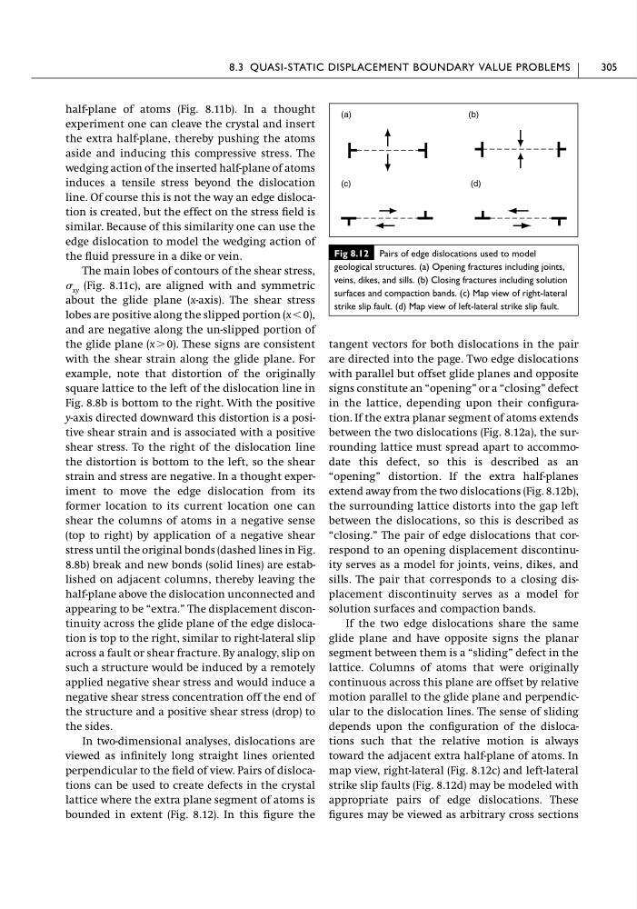
perpendicular to the field of view. Pairs of dislocations can be used to create defects in the crystal
lattice where the extra plane segment of atoms is
bounded in extent (Fig. 8.12). In this figure the
tangent vectors for both dislocations in the pair
are directed into the page. Two edge dislocations
with parallel but offset glide planes and opposite
signs constitute an “opening” or a “closing” defect
in the lattice, depending upon their configuration. If the extra planar segment of atoms extends
between the two dislocations (Fig. 8.12a), the surrounding lattice must spread apart to accommodate this defect, so this is described as an
“opening” distortion. If the extra half-planes
extend away from the two dislocations (Fig. 8.12b),
the surrounding lattice distorts into the gap left
between the dislocations, so this is described as
“closing.” The pair of edge dislocations that correspond to an opening displacement discontinuity serves as a model for joints, veins, dikes, and
sills. The pair that corresponds to a closing displacement discontinuity serves as a model for
solution surfaces and compaction bands.
If the two edge dislocations share the same
glide plane and have opposite signs the planar
segment between them is a “sliding” defect in the
lattice. Columns of atoms that were originally
continuous across this plane are offset by relative
motion parallel to the glide plane and perpendicular to the dislocation lines. The sense of sliding
depends upon the configuration of the dislocations such that the relative motion is always
toward the adjacent extra half-plane of atoms. In
map view, right-lateral (Fig. 8.12c) and left-lateral
strike slip faults (Fig. 8.12d) may be modeled with
appropriate pairs of edge dislocations. These
figures may be viewed as arbitrary cross sections
8.3 QUASI-STATIC DISPLACEMENT BOUNDARY VALUE PROBLEMS
305
Fig 8.12 Pairs of edge dislocations used to model
geological structures. (a) Opening fractures including joints,
veins, dikes, and sills. (b) Closing fractures including solution
surfaces and compaction bands. (c) Map view of right-lateral
strike slip fault. (d) Map view of left-lateral strike slip fault.
(a)
(b)
(c)
(d)
experiment one can cleave the crystal and insert
the extra half-plane, thereby pushing the atoms
aside and inducing this compressive stress. The
wedging action of the inserted half-plane of atoms
induces a tensile stress beyond the dislocation
line. Of course this is not the way an edge dislocation is created, but the effect on the stress field is
similar. Because of this similarity one can use the
edge dislocation to model the wedging action of
the fluid pressure in a dike or vein.
The main lobes of contours of the shear stress,
xy (Fig. 8.11c), are aligned with and symmetric
about the glide plane (x-axis). The shear stress
lobes are positive along the slipped portion (xϽ 0),
and are negative along the un-slipped portion of
the glide plane (x Ͼ 0). These signs are consistent
with the shear strain along the glide plane. For
example, note that distortion of the originally
square lattice to the left of the dislocation line in
Fig. 8.8b is bottom to the right. With the positive
y-axis directed downward this distortion is a positive shear strain and is associated with a positive
shear stress. To the right of the dislocation line
the distortion is bottom to the left, so the shear
strain and stress are negative. In a thought experiment to move the edge dislocation from its
former location to its current location one can
shear the columns of atoms in a negative sense
(top to right) by application of a negative shear
stress until the original bonds (dashed lines in Fig.
8.8b) break and new bonds (solid lines) are established on adjacent columns, thereby leaving the
half-plane above the dislocation unconnected and
appearing to be “extra.” The displacement discontinuity across the glide plane of the edge dislocation is top to the right, similar to right-lateral slip
across a fault or shear fracture. By analogy, slip on
such a structure would be induced by a remotely
applied negative shear stress and would induce a
negative shear stress concentration off the end of
the structure and a positive shear stress (drop) to
the sides.
In two-dimensional analyses, dislocations are
viewed as infinitely long straight lines oriented
perpendicular to the field of view. Pairs of dislocations can be used to create defects in the crystal
lattice where the extra plane segment of atoms is
bounded in extent (Fig. 8.12). In this figure the
tangent vectors for both dislocations in the pair
are directed into the page. Two edge dislocations
with parallel but offset glide planes and opposite
signs constitute an “opening” or a “closing” defect
in the lattice, depending upon their configuration. If the extra planar segment of atoms extends
between the two dislocations (Fig. 8.12a), the surrounding lattice must spread apart to accommodate this defect, so this is described as an
“opening” distortion. If the extra half-planes
extend away from the two dislocations (Fig. 8.12b),
the surrounding lattice distorts into the gap left
between the dislocations, so this is described as
“closing.” The pair of edge dislocations that correspond to an opening displacement discontinuity serves as a model for joints, veins, dikes, and
sills. The pair that corresponds to a closing displacement discontinuity serves as a model for
solution surfaces and compaction bands.
If the two edge dislocations share the same
glide plane and have opposite signs the planar
segment between them is a “sliding” defect in the
lattice. Columns of atoms that were originally
continuous across this plane are offset by relative
motion parallel to the glide plane and perpendicular to the dislocation lines. The sense of sliding
depends upon the configuration of the dislocations such that the relative motion is always
toward the adjacent extra half-plane of atoms. In
map view, right-lateral (Fig. 8.12c) and left-lateral
strike slip faults (Fig. 8.12d) may be modeled with
appropriate pairs of edge dislocations. These
figures may be viewed as arbitrary cross sections
8.3 QUASI-STATIC DISPLACEMENT BOUNDARY VALUE PROBLEMS
305
Fig 8.12 Pairs of edge dislocations used to model
geological structures. (a) Opening fractures including joints,
veins, dikes, and sills. (b) Closing fractures including solution
surfaces and compaction bands. (c) Map view of right-lateral
strike slip fault. (d) Map view of left-lateral strike slip fault.
(a)
(b)
(c)
(d)