

(x, y)-plane. Noting that x ϭ r cos and y ϭ r sin ,
the numerators are proportional to br
3 , so the
strain components are proportional to b/r. Thus,
as the distance to the dislocation line becomes
very small, the strain becomes very large. In fact,
there is a mathematical singularity in all of the
strain components at the dislocation line (as r →
0, ij → ϱ). This is mathematically correct, but is
non-physical, so we restrict attention to the region
outside the dislocation core (r Ͼ 5b), where the
strain components are finite.
Hooke’s Law for plane strain conditions (8.34)
is used to determine the stress components:
(8.41)
(8.42)
(8.43)
Like the strain components, the stress components are proportional to b/r, so they also are singular at the dislocation line. As mentioned above
we restrict attention to the region outside the dislocation core where the stress components are
less than the strength of the material. Note that
the presence of the edge dislocation alters the
normal stress, zz , parallel to the dislocation line
according to (8.35).
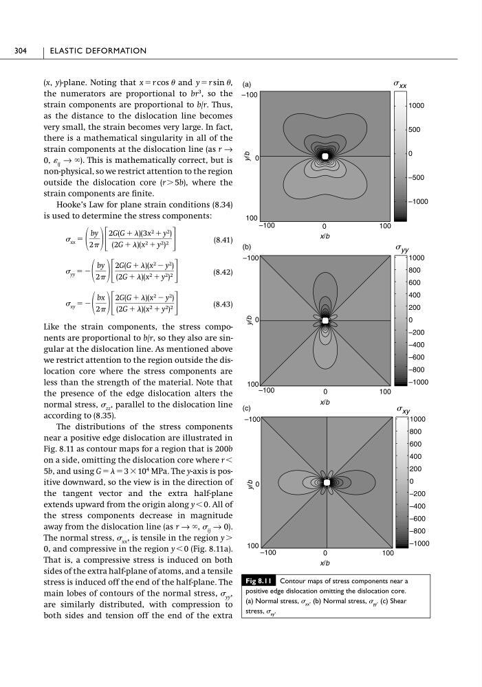
The distributions of the stress components
near a positive edge dislocation are illustrated in
Fig. 8.11 as contour maps for a region that is 200b
on a side, omitting the dislocation core where r Ͻ
5b, and using G ϭ ϭ 3 ϫ 10
4 MPa. The y-axis is positive downward, so the view is in the direction of
the tangent vector and the extra half-plane
extends upward from the origin along y Ͻ 0. All of
the stress components decrease in magnitude
away from the dislocation line (as r → ϱ, ij → 0).
The normal stress, xx , is tensile in the region y Ͼ
0, and compressive in the region y Ͻ 0 (Fig. 8.11a).
That is, a compressive stress is induced on both
sides of the extra half-plane of atoms, and a tensile
stress is induced off the end of the half-plane. The
main lobes of contours of the normal stress, yy ,
are similarly distributed, with compression to
both sides and tension off the end of the extra
xy ϭ Ϫ
bx
2 ΄
2G(G ϩ )(x 2 Ϫ y 2 )
(2G ϩ )(x 2 ϩ y 2 ) 2 ΅
yy ϭ Ϫ
by
2 ΄
2G(G ϩ )(x 2 Ϫ y 2 )
(2G ϩ )(x 2 ϩ y 2 ) 2 ΅
xx ϭ
by
2 ΄
2G(G ϩ )(3x 2 ϩ y 2 )
(2G ϩ )(x 2 ϩ y 2 ) 2 ΅
304
ELASTIC DEFORMATION
Fig 8.11 Contour maps of stress components near a
positive edge dislocation omitting the dislocation core.
(a) Normal stress, xx . (b) Normal stress, yy . (c) Shear
stress, xy .
100
0
100
–100
0
–100
1000
500
0
–500
–1000
y/b
y/b
y/b
x/b
x/b
x/b
0
100
0
–100
1000
800
600
400
200
0
–200
–400
–600
–800
–1000
1000
800
600
400
200
0
–200
–400
–600
–800
–1000
0
100
0
–100
s xy
s yy
s xx
–100
100
–100
100
(a)
(b)
(c)
the numerators are proportional to br
3 , so the
strain components are proportional to b/r. Thus,
as the distance to the dislocation line becomes
very small, the strain becomes very large. In fact,
there is a mathematical singularity in all of the
strain components at the dislocation line (as r →
0, ij → ϱ). This is mathematically correct, but is
non-physical, so we restrict attention to the region
outside the dislocation core (r Ͼ 5b), where the
strain components are finite.
Hooke’s Law for plane strain conditions (8.34)
is used to determine the stress components:
(8.41)
(8.42)
(8.43)
Like the strain components, the stress components are proportional to b/r, so they also are singular at the dislocation line. As mentioned above
we restrict attention to the region outside the dislocation core where the stress components are
less than the strength of the material. Note that
the presence of the edge dislocation alters the
normal stress, zz , parallel to the dislocation line
according to (8.35).
The distributions of the stress components
near a positive edge dislocation are illustrated in
Fig. 8.11 as contour maps for a region that is 200b
on a side, omitting the dislocation core where r Ͻ
5b, and using G ϭ ϭ 3 ϫ 10
4 MPa. The y-axis is positive downward, so the view is in the direction of
the tangent vector and the extra half-plane
extends upward from the origin along y Ͻ 0. All of
the stress components decrease in magnitude
away from the dislocation line (as r → ϱ, ij → 0).
The normal stress, xx , is tensile in the region y Ͼ
0, and compressive in the region y Ͻ 0 (Fig. 8.11a).
That is, a compressive stress is induced on both
sides of the extra half-plane of atoms, and a tensile
stress is induced off the end of the half-plane. The
main lobes of contours of the normal stress, yy ,
are similarly distributed, with compression to
both sides and tension off the end of the extra
xy ϭ Ϫ
bx
2 ΄
2G(G ϩ )(x 2 Ϫ y 2 )
(2G ϩ )(x 2 ϩ y 2 ) 2 ΅
yy ϭ Ϫ
by
2 ΄
2G(G ϩ )(x 2 Ϫ y 2 )
(2G ϩ )(x 2 ϩ y 2 ) 2 ΅
xx ϭ
by
2 ΄
2G(G ϩ )(3x 2 ϩ y 2 )
(2G ϩ )(x 2 ϩ y 2 ) 2 ΅
304
ELASTIC DEFORMATION
Fig 8.11 Contour maps of stress components near a
positive edge dislocation omitting the dislocation core.
(a) Normal stress, xx . (b) Normal stress, yy . (c) Shear
stress, xy .
100
0
100
–100
0
–100
1000
500
0
–500
–1000
y/b
y/b
y/b
x/b
x/b
x/b
0
100
0
–100
1000
800
600
400
200
0
–200
–400
–600
–800
–1000
1000
800
600
400
200
0
–200
–400
–600
–800
–1000
0
100
0
–100
s xy
s yy
s xx
–100
100
–100
100
(a)
(b)
(c)