

is made with an equal number of steps (from atom
to atom) along parallel paths. For example, starting at the arbitrarily chosen atom “s,” one could
take four steps down, five steps to the left, four
steps up, and five steps to the right, finishing at
atom “f.” If the lattice were undistorted, “s” and
“f” would be the same atom. The fact that the
circuit does not close reveals the presence of the
edge dislocation. The magnitude of the vector, b ϭ
b x e x , extending from atom “f” to atom “s” measures the distortion of the lattice and this vector
is directed in the positive x-coordinate direction,
i.e. b x Ͼ 0. This is called the Burgers vector of the dislocation. For an edge dislocation the Burgers
vector is always perpendicular to the dislocation
line. For the so-called screw dislocation the Burgers
vector is parallel to the dislocation line. Dislocation loops (Fig. 8.8a) are composed of segments
of edge, screw, and mixed dislocations.
An edge dislocation line can move through a
crystalline solid parallel to the plane containing
the tangent vector and the Burgers vector. This
plane is called the glide plane. A fundamental
feature of the deformation associated with the
edge dislocation is that the displacement field is
discontinuous across that portion of the glide
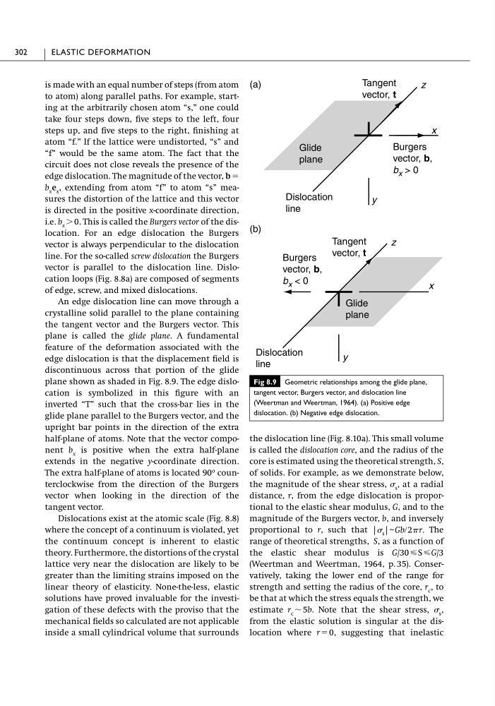
plane shown as shaded in Fig. 8.9. The edge dislocation is symbolized in this figure with an
inverted “T” such that the cross-bar lies in the
glide plane parallel to the Burgers vector, and the
upright bar points in the direction of the extra
half-plane of atoms. Note that the vector component b x is positive when the extra half-plane
extends in the negative y-coordinate direction.
The extra half-plane of atoms is located 90
o counterclockwise from the direction of the Burgers
vector when looking in the direction of the
tangent vector.
Dislocations exist at the atomic scale (Fig. 8.8)
where the concept of a continuum is violated, yet
the continuum concept is inherent to elastic
theory. Furthermore, the distortions of the crystal
lattice very near the dislocation are likely to be
greater than the limiting strains imposed on the
linear theory of elasticity. None-the-less, elastic
solutions have proved invaluable for the investigation of these defects with the proviso that the
mechanical fields so calculated are not applicable
inside a small cylindrical volume that surrounds
the dislocation line (Fig. 8.10a). This small volume
is called the dislocation core, and the radius of the
core is estimated using the theoretical strength, S,
of solids. For example, as we demonstrate below,
the magnitude of the shear stress, s , at a radial
distance, r, from the edge dislocation is proportional to the elastic shear modulus, G, and to the
magnitude of the Burgers vector, b, and inversely
proportional to r, such that
The
range of theoretical strengths, S, as a function of
the elastic shear modulus is G/30 рS рG/3
(Weertman and Weertman, 1964, p. 35). Conservatively, taking the lower end of the range for
strength and setting the radius of the core, r c , to
be that at which the stress equals the strength, we
estimate r c ϳ 5b. Note that the shear stress, s ,
from the elastic solution is singular at the dislocation where r ϭ 0, suggesting that inelastic
| s | ~ Gbր2 r.
302
ELASTIC DEFORMATION
Fig 8.9 Geometric relationships among the glide plane,
tangent vector, Burgers vector, and dislocation line
(Weertman and Weertman, 1964). (a) Positive edge
dislocation. (b) Negative edge dislocation.
x
y
z
Burgers
vector, b,
b x > 0
x
y
z
Burgers
vector, b,
b x < 0
Glide
plane
Dislocation
line
Tangent
vector, t
Tangent
vector, t
Glide
plane
Dislocation
line
(a)
(b)
to atom) along parallel paths. For example, starting at the arbitrarily chosen atom “s,” one could
take four steps down, five steps to the left, four
steps up, and five steps to the right, finishing at
atom “f.” If the lattice were undistorted, “s” and
“f” would be the same atom. The fact that the
circuit does not close reveals the presence of the
edge dislocation. The magnitude of the vector, b ϭ
b x e x , extending from atom “f” to atom “s” measures the distortion of the lattice and this vector
is directed in the positive x-coordinate direction,
i.e. b x Ͼ 0. This is called the Burgers vector of the dislocation. For an edge dislocation the Burgers
vector is always perpendicular to the dislocation
line. For the so-called screw dislocation the Burgers
vector is parallel to the dislocation line. Dislocation loops (Fig. 8.8a) are composed of segments
of edge, screw, and mixed dislocations.
An edge dislocation line can move through a
crystalline solid parallel to the plane containing
the tangent vector and the Burgers vector. This
plane is called the glide plane. A fundamental
feature of the deformation associated with the
edge dislocation is that the displacement field is
discontinuous across that portion of the glide
plane shown as shaded in Fig. 8.9. The edge dislocation is symbolized in this figure with an
inverted “T” such that the cross-bar lies in the
glide plane parallel to the Burgers vector, and the
upright bar points in the direction of the extra
half-plane of atoms. Note that the vector component b x is positive when the extra half-plane
extends in the negative y-coordinate direction.
The extra half-plane of atoms is located 90
o counterclockwise from the direction of the Burgers
vector when looking in the direction of the
tangent vector.
Dislocations exist at the atomic scale (Fig. 8.8)
where the concept of a continuum is violated, yet
the continuum concept is inherent to elastic
theory. Furthermore, the distortions of the crystal
lattice very near the dislocation are likely to be
greater than the limiting strains imposed on the
linear theory of elasticity. None-the-less, elastic
solutions have proved invaluable for the investigation of these defects with the proviso that the
mechanical fields so calculated are not applicable
inside a small cylindrical volume that surrounds
the dislocation line (Fig. 8.10a). This small volume
is called the dislocation core, and the radius of the
core is estimated using the theoretical strength, S,
of solids. For example, as we demonstrate below,
the magnitude of the shear stress, s , at a radial
distance, r, from the edge dislocation is proportional to the elastic shear modulus, G, and to the
magnitude of the Burgers vector, b, and inversely
proportional to r, such that
The
range of theoretical strengths, S, as a function of
the elastic shear modulus is G/30 рS рG/3
(Weertman and Weertman, 1964, p. 35). Conservatively, taking the lower end of the range for
strength and setting the radius of the core, r c , to
be that at which the stress equals the strength, we
estimate r c ϳ 5b. Note that the shear stress, s ,
from the elastic solution is singular at the dislocation where r ϭ 0, suggesting that inelastic
| s | ~ Gbր2 r.
302
ELASTIC DEFORMATION
Fig 8.9 Geometric relationships among the glide plane,
tangent vector, Burgers vector, and dislocation line
(Weertman and Weertman, 1964). (a) Positive edge
dislocation. (b) Negative edge dislocation.
x
y
z
Burgers
vector, b,
b x > 0
x
y
z
Burgers
vector, b,
b x < 0
Glide
plane
Dislocation
line
Tangent
vector, t
Tangent
vector, t
Glide
plane
Dislocation
line
(a)
(b)