

F ϭKu
(8.1)
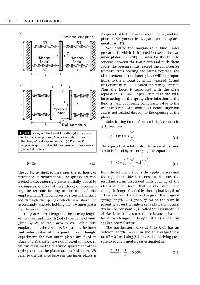
The spring constant, K, measures the stiffness, or
resistance, to deformation. The springs are connected to two outer rigid plates, initially loaded by
a compressive stress of magnitude, C, representing the tectonic loading at the time of dike
emplacement. This compressive stress is transmitted through the springs (which have shortened
accordingly), thereby holding the two inner plates
tightly pressed together.
The plates have a length, L, the outcrop length
of the dike, and a width (out of the plane of view)
given by W, so their area is WL. Before dike
emplacement, the distance, L, separates the inner
and outer plates. At this point in our thought
experiment the two outer plates are fixed in
place and thereafter are not allowed to move, so
we can measure the relative displacement of the
spring ends as the plates are pushed apart. We
refer to the distance between the inner plates as
T, equivalent to the thickness of the dike, and the
plates move symmetrically apart, so the displacement is u ϭ T/2.
We idealize the magma as a fluid under
pressure, P, which is injected between the two
inner plates (Fig. 8.2b). In order for this fluid to
squeeze between the two plates and push them
apart, the pressure must exceed the compressive
tectonic stress holding the plates together. The
displacement of the inner plates will be proportional to the amount by which P exceeds C, and
this quantity, P Ϫ C, is called the driving pressure.
Thus the force, F, associated with the plate
separation is F ϭ (P Ϫ C)WL. Note that the total
force acting on the spring after injection of the
fluid is PWL, but spring compression due to the
tectonic force, CWL, took place before injection
and is not related directly to the opening of the
plates.
Substituting for the force and displacement in
(8.1), we have:
(8.2)
The equivalent relationship between stress and
strain is found by rearranging this equation:
(8.3)
Here the left-hand side is the applied stress and
the right-hand side is a constant, E, times the
resultant strain associated with opening of the
idealized dike. Recall that normal strain is a
change in length divided by the original length of
a line element. Here the change in the original
spring length, L, is given by T/2, so the term in
parentheses on the right-hand side is the normal
strain. The constant, E, is called Young’s modulus
of elasticity. It measures the resistance of a material to change in length (strain) under an
applied normal stress.
The northeastern dike at Ship Rock has an
outcrop length L ϭ 2900 m and an average thickness T ϭ 2.3 m. Using (8.3) the ratio of driving pressure to Young’s modulus is estimated as:
(8.4)
(P Ϫ C)
E
Ϸ
T
2L
Ϸ 0.0004
(P Ϫ C) ϭ
K
W
Tր2
L
ϭ E
Tր2
L
(P Ϫ C)WL ϭ K
T
2
290
ELASTIC DEFORMATION
Fig 8.2 Spring and block model for dike. (a) Before dike
emplacement compression, C, acts across the prospective
dike plane; K/2 is the spring constant. (b) Pressure, P,
compresses springs and model dike opens with displacement,
u, in both directions.
K/2
K/2
K/2
K/2
“Mancos
Shale”
“Mancos
Shale”
L
L
P
“Igneous
dike”
Displacement, u
L
L
(a)
(b)
“Potential dike plane”
C
T
y
x
(8.1)
The spring constant, K, measures the stiffness, or
resistance, to deformation. The springs are connected to two outer rigid plates, initially loaded by
a compressive stress of magnitude, C, representing the tectonic loading at the time of dike
emplacement. This compressive stress is transmitted through the springs (which have shortened
accordingly), thereby holding the two inner plates
tightly pressed together.
The plates have a length, L, the outcrop length
of the dike, and a width (out of the plane of view)
given by W, so their area is WL. Before dike
emplacement, the distance, L, separates the inner
and outer plates. At this point in our thought
experiment the two outer plates are fixed in
place and thereafter are not allowed to move, so
we can measure the relative displacement of the
spring ends as the plates are pushed apart. We
refer to the distance between the inner plates as
T, equivalent to the thickness of the dike, and the
plates move symmetrically apart, so the displacement is u ϭ T/2.
We idealize the magma as a fluid under
pressure, P, which is injected between the two
inner plates (Fig. 8.2b). In order for this fluid to
squeeze between the two plates and push them
apart, the pressure must exceed the compressive
tectonic stress holding the plates together. The
displacement of the inner plates will be proportional to the amount by which P exceeds C, and
this quantity, P Ϫ C, is called the driving pressure.
Thus the force, F, associated with the plate
separation is F ϭ (P Ϫ C)WL. Note that the total
force acting on the spring after injection of the
fluid is PWL, but spring compression due to the
tectonic force, CWL, took place before injection
and is not related directly to the opening of the
plates.
Substituting for the force and displacement in
(8.1), we have:
(8.2)
The equivalent relationship between stress and
strain is found by rearranging this equation:
(8.3)
Here the left-hand side is the applied stress and
the right-hand side is a constant, E, times the
resultant strain associated with opening of the
idealized dike. Recall that normal strain is a
change in length divided by the original length of
a line element. Here the change in the original
spring length, L, is given by T/2, so the term in
parentheses on the right-hand side is the normal
strain. The constant, E, is called Young’s modulus
of elasticity. It measures the resistance of a material to change in length (strain) under an
applied normal stress.
The northeastern dike at Ship Rock has an
outcrop length L ϭ 2900 m and an average thickness T ϭ 2.3 m. Using (8.3) the ratio of driving pressure to Young’s modulus is estimated as:
(8.4)
(P Ϫ C)
E
Ϸ
T
2L
Ϸ 0.0004
(P Ϫ C) ϭ
K
W
Tր2
L
ϭ E
Tր2
L
(P Ϫ C)WL ϭ K
T
2
290
ELASTIC DEFORMATION
Fig 8.2 Spring and block model for dike. (a) Before dike
emplacement compression, C, acts across the prospective
dike plane; K/2 is the spring constant. (b) Pressure, P,
compresses springs and model dike opens with displacement,
u, in both directions.
K/2
K/2
K/2
K/2
“Mancos
Shale”
“Mancos
Shale”
L
L
P
“Igneous
dike”
Displacement, u
L
L
(a)
(b)
“Potential dike plane”
C
T
y
x