

(z � 0), along with the gravitational force components per unit volume, F i , are given by:
(6.104)
This state of stress is referred to as a state of perfect
confinement.
The relationship between the vertical and horizontal components of stress (6.104) depends upon
an elastic property called Poisson’s ratio, �. For this
discussion it is sufficient to understand that
Poisson’s ratio is a dimensionless number with
values that range between 0 and 1/2. For � � 0.25, the
value used for the models illustrated in Fig. 6.30, the
horizontal stress is one-third of the vertical stress
according to (6.104). For � � 1/3, the horizontal stress
is one-half of the vertical stress, and as � goes to 1/2,
the vertical and horizontal stress components
become equal. Thus, Anderson’s standard state is
consistent with an elastic, perfectly constrained
rock mass only if Poisson’s ratio is equal to 1/2.
6.3.2 Measurement of in-situ stress:
hydraulic fractures and wellbore
breakouts
Two common methods for stress measurement at
depth in the Earth’s crust involve data taken from
wellbores. The first method is based upon perturbing the local state of stress near a wellbore by
increasing the internal fluid pressure until the
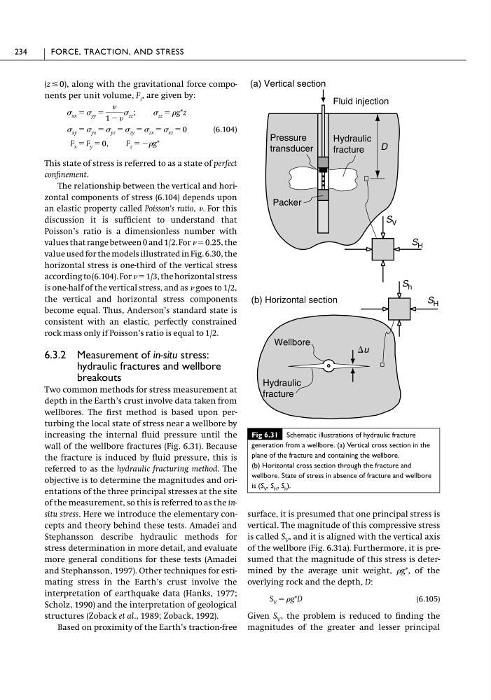
wall of the wellbore fractures (Fig. 6.31). Because
the fracture is induced by fluid pressure, this is
referred to as the hydraulic fracturing method. The
objective is to determine the magnitudes and orientations of the three principal stresses at the site
of the measurement, so this is referred to as the insitu stress. Here we introduce the elementary concepts and theory behind these tests. Amadei and
Stephansson describe hydraulic methods for
stress determination in more detail, and evaluate
more general conditions for these tests (Amadei
and Stephansson, 1997). Other techniques for estimating stress in the Earth’s crust involve the
interpretation of earthquake data (Hanks, 1977;
Scholz, 1990) and the interpretation of geological
structures (Zoback et al., 1989; Zoback, 1992).
Based on proximity of the Earth’s traction-free
F x � F y � 0, F z � ��g*
� xy � � yx � � yz � � zy � � zx � � xz � 0
� xx � � yy �
�
1 � �
� zz ; � zz � �g*z
surface, it is presumed that one principal stress is
vertical. The magnitude of this compressive stress
is called S V , and it is aligned with the vertical axis
of the wellbore (Fig. 6.31a). Furthermore, it is presumed that the magnitude of this stress is determined by the average unit weight, �g*, of the
overlying rock and the depth, D:
(6.105)
Given S V , the problem is reduced to finding the
magnitudes of the greater and lesser principal
S V � �g*D
234
FORCE, TRACTION, AND STRESS
Fig 6.31 Schematic illustrations of hydraulic fracture
generation from a wellbore. (a) Vertical cross section in the
plane of the fracture and containing the wellbore.
(b) Horizontal cross section through the fracture and
wellbore. State of stress in absence of fracture and wellbore
is (S V , S H , S h ).
Fluid injection
Hydraulic
fracture
Packer
Pressure
transducer
D
(b) Horizontal section
Hydraulic
fracture
Wellbore
(a) Vertical section
S V
S H
S h
S H
�u
(6.104)
This state of stress is referred to as a state of perfect
confinement.
The relationship between the vertical and horizontal components of stress (6.104) depends upon
an elastic property called Poisson’s ratio, �. For this
discussion it is sufficient to understand that
Poisson’s ratio is a dimensionless number with
values that range between 0 and 1/2. For � � 0.25, the
value used for the models illustrated in Fig. 6.30, the
horizontal stress is one-third of the vertical stress
according to (6.104). For � � 1/3, the horizontal stress
is one-half of the vertical stress, and as � goes to 1/2,
the vertical and horizontal stress components
become equal. Thus, Anderson’s standard state is
consistent with an elastic, perfectly constrained
rock mass only if Poisson’s ratio is equal to 1/2.
6.3.2 Measurement of in-situ stress:
hydraulic fractures and wellbore
breakouts
Two common methods for stress measurement at
depth in the Earth’s crust involve data taken from
wellbores. The first method is based upon perturbing the local state of stress near a wellbore by
increasing the internal fluid pressure until the
wall of the wellbore fractures (Fig. 6.31). Because
the fracture is induced by fluid pressure, this is
referred to as the hydraulic fracturing method. The
objective is to determine the magnitudes and orientations of the three principal stresses at the site
of the measurement, so this is referred to as the insitu stress. Here we introduce the elementary concepts and theory behind these tests. Amadei and
Stephansson describe hydraulic methods for
stress determination in more detail, and evaluate
more general conditions for these tests (Amadei
and Stephansson, 1997). Other techniques for estimating stress in the Earth’s crust involve the
interpretation of earthquake data (Hanks, 1977;
Scholz, 1990) and the interpretation of geological
structures (Zoback et al., 1989; Zoback, 1992).
Based on proximity of the Earth’s traction-free
F x � F y � 0, F z � ��g*
� xy � � yx � � yz � � zy � � zx � � xz � 0
� xx � � yy �
�
1 � �
� zz ; � zz � �g*z
surface, it is presumed that one principal stress is
vertical. The magnitude of this compressive stress
is called S V , and it is aligned with the vertical axis
of the wellbore (Fig. 6.31a). Furthermore, it is presumed that the magnitude of this stress is determined by the average unit weight, �g*, of the
overlying rock and the depth, D:
(6.105)
Given S V , the problem is reduced to finding the
magnitudes of the greater and lesser principal
S V � �g*D
234
FORCE, TRACTION, AND STRESS
Fig 6.31 Schematic illustrations of hydraulic fracture
generation from a wellbore. (a) Vertical cross section in the
plane of the fracture and containing the wellbore.
(b) Horizontal cross section through the fracture and
wellbore. State of stress in absence of fracture and wellbore
is (S V , S H , S h ).
Fluid injection
Hydraulic
fracture
Packer
Pressure
transducer
D
(b) Horizontal section
Hydraulic
fracture
Wellbore
(a) Vertical section
S V
S H
S h
S H
�u