

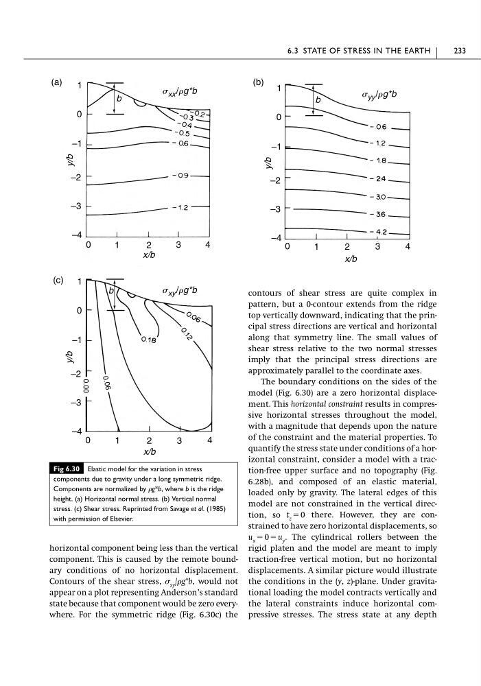
horizontal component being less than the vertical
component. This is caused by the remote boundary conditions of no horizontal displacement.
Contours of the shear stress, xy /g*b, would not
appear on a plot representing Anderson’s standard
state because that component would be zero everywhere. For the symmetric ridge (Fig. 6.30c) the
contours of shear stress are quite complex in
pattern, but a 0-contour extends from the ridge
top vertically downward, indicating that the principal stress directions are vertical and horizontal
along that symmetry line. The small values of
shear stress relative to the two normal stresses
imply that the principal stress directions are
approximately parallel to the coordinate axes.
The boundary conditions on the sides of the
model (Fig. 6.30) are a zero horizontal displacement. This horizontal constraint results in compressive horizontal stresses throughout the model,
with a magnitude that depends upon the nature
of the constraint and the material properties. To
quantify the stress state under conditions of a horizontal constraint, consider a model with a traction-free upper surface and no topography (Fig.
6.28b), and composed of an elastic material,
loaded only by gravity. The lateral edges of this
model are not constrained in the vertical direction, so t z ϭ 0 there. However, they are constrained to have zero horizontal displacements, so
u x ϭ 0 ϭ u y . The cylindrical rollers between the
rigid platen and the model are meant to imply
traction-free vertical motion, but no horizontal
displacements. A similar picture would illustrate
the conditions in the (y, z)-plane. Under gravitational loading the model contracts vertically and
the lateral constraints induce horizontal compressive stresses. The stress state at any depth
6.3 STATE OF STRESS IN THE EARTH
233
Fig 6.30 Elastic model for the variation in stress
components due to gravity under a long symmetric ridge.
Components are normalized by g*b, where b is the ridge
height. (a) Horizontal normal stress. (b) Vertical normal
stress. (c) Shear stress. Reprinted from Savage et al. (1985)
with permission of Elsevier.
(a)
(c)
1
0
–1
–2
–3
–4
0
1
2
3
4
x/b
y/b
1
0
–1
–2
–3
–4
0
1
2
3
4
x/b
y/b
S xx /Rg*b
S xy /Rg*b
b
b
0.
06
0.00
(b) 1
0
–1
–2
–3
–4 0
1
2
3
4
x/b
y/b
S yy /Rg*b
b
component. This is caused by the remote boundary conditions of no horizontal displacement.
Contours of the shear stress, xy /g*b, would not
appear on a plot representing Anderson’s standard
state because that component would be zero everywhere. For the symmetric ridge (Fig. 6.30c) the
contours of shear stress are quite complex in
pattern, but a 0-contour extends from the ridge
top vertically downward, indicating that the principal stress directions are vertical and horizontal
along that symmetry line. The small values of
shear stress relative to the two normal stresses
imply that the principal stress directions are
approximately parallel to the coordinate axes.
The boundary conditions on the sides of the
model (Fig. 6.30) are a zero horizontal displacement. This horizontal constraint results in compressive horizontal stresses throughout the model,
with a magnitude that depends upon the nature
of the constraint and the material properties. To
quantify the stress state under conditions of a horizontal constraint, consider a model with a traction-free upper surface and no topography (Fig.
6.28b), and composed of an elastic material,
loaded only by gravity. The lateral edges of this
model are not constrained in the vertical direction, so t z ϭ 0 there. However, they are constrained to have zero horizontal displacements, so
u x ϭ 0 ϭ u y . The cylindrical rollers between the
rigid platen and the model are meant to imply
traction-free vertical motion, but no horizontal
displacements. A similar picture would illustrate
the conditions in the (y, z)-plane. Under gravitational loading the model contracts vertically and
the lateral constraints induce horizontal compressive stresses. The stress state at any depth
6.3 STATE OF STRESS IN THE EARTH
233
Fig 6.30 Elastic model for the variation in stress
components due to gravity under a long symmetric ridge.
Components are normalized by g*b, where b is the ridge
height. (a) Horizontal normal stress. (b) Vertical normal
stress. (c) Shear stress. Reprinted from Savage et al. (1985)
with permission of Elsevier.
(a)
(c)
1
0
–1
–2
–3
–4
0
1
2
3
4
x/b
y/b
1
0
–1
–2
–3
–4
0
1
2
3
4
x/b
y/b
S xx /Rg*b
S xy /Rg*b
b
b
0.
06
0.00
(b) 1
0
–1
–2
–3
–4 0
1
2
3
4
x/b
y/b
S yy /Rg*b
b