

(6.81)
Equation (6.80) then takes the form (Jaeger and
Cook, 1979):
(6.82)
Note that the shear stress is a function of the principal stress differences.
The goal is to identify the extreme values of
the shear stress as a function of the components
of n. However, these three components are not
independent, so we use (6.17) to eliminate n z from
(6.82) and write the shear stress as a function of
the two independent variables, n x and n y :
(6.83)
The maximum and minimum, or stationary,
values of the shear stress are found by taking the
derivatives of (6.83) with respect to n x and n y :
(6.84)
The right-hand sides of (6.84) are zero if n x ϭ 0 ϭ n y ,
but this refers to a principal plane on which the
shear stress is zero (minimum).
Taking n x ϭ 0 the right-hand side of the first of
(6.84) is zero and the second reduces to:
(6.85)
For 2 Ϫ 3 0, the second term in parentheses
must be zero, and this requires
Using (6.17)
we find
and conclude that the components
of n for the planes carrying this shear stress
are:
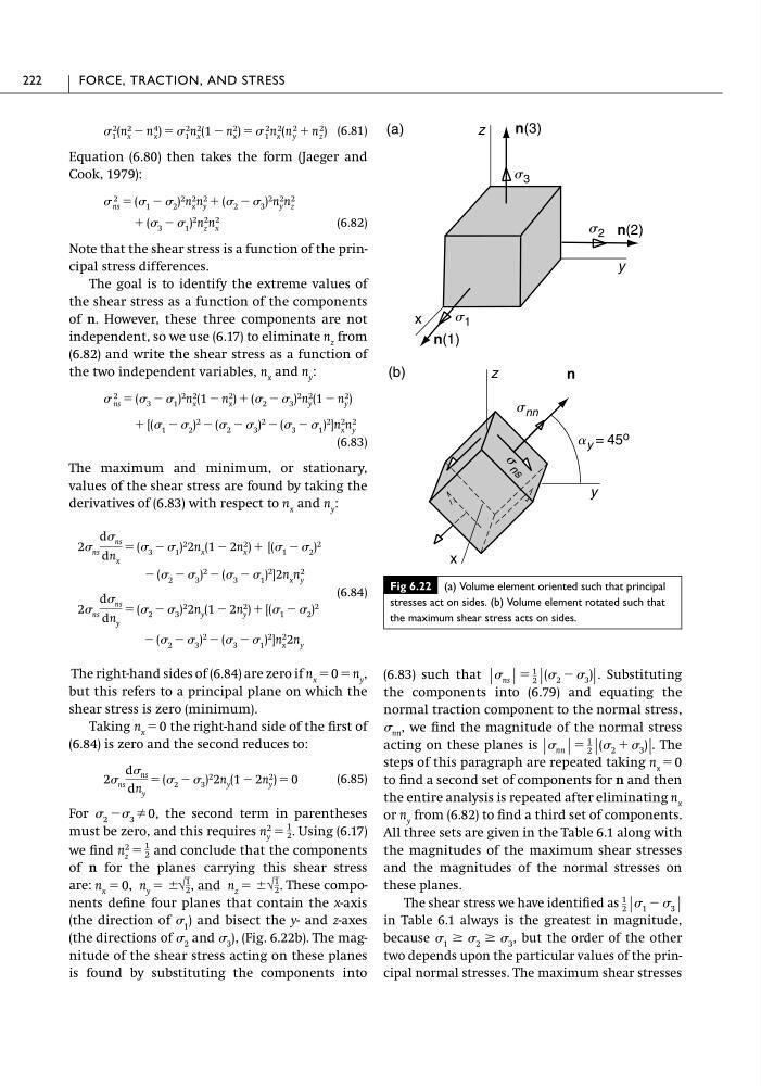
These components define four planes that contain the x-axis
(the direction of 1 ) and bisect the y- and z-axes
(the directions of 2 and 3 ), (Fig. 6.22b). The magnitude of the shear stress acting on these planes
is found by substituting the components into
n x ϭ 0, n y ϭ Ϯ√
1
2 , and n z ϭ Ϯ√
1
2 .
n
2
z
ϭ
1
2
n
2
y
ϭ
1
2 .
2 ns
d ns
dn y
ϭ ( 2 Ϫ 3 ) 2 2n y (1 Ϫ 2n 2
y ) ϭ 0
Ϫ ( 2 Ϫ 3 )
2 Ϫ ( 3 Ϫ 1 )
2 ]n
2
x
2n y
2 ns
d ns
dn y
ϭ ( 2 Ϫ 3 ) 2 2n y (1 Ϫ 2n 2
y ) ϩ [( 1 Ϫ 2 ) 2
Ϫ ( 2 Ϫ 3 )
2 Ϫ ( 3 Ϫ 1 )
2
]2n x n
2
y
2 ns
d ns
dn x
ϭ ( 3 Ϫ 1 ) 2 2n x (1 Ϫ 2n 2
x ) ϩ [( 1 Ϫ 2 ) 2
ϩ [( 1 Ϫ 2 )
2 Ϫ ( 2 Ϫ 3 )
2 Ϫ ( 3 Ϫ 1 )
2
]n
2
x
n
2
y
2
ns ϭ ( 3 Ϫ 1 ) 2 n 2
x (1 Ϫ n 2
x ) ϩ ( 2 Ϫ 3 ) 2 n 2
y (1 Ϫ n 2
y )
ϩ ( 3 Ϫ 1 )
2 n
2
z
n
2
x
2
ns ϭ ( 1 Ϫ 2 ) 2 n 2
x n 2
y ϩ ( 2 Ϫ 3 ) 2 n 2
y n 2
z
2
1 (n 2
x Ϫ n 4
x ) ϭ 2
1 n 2
x (1 Ϫ n 2
x ) ϭ 2
1 n 2
x (n 2
y ϩ n 2
z )
(6.83) such that
. Substituting
the components into (6.79) and equating the
normal traction component to the normal stress,
nn , we find the magnitude of the normal stress
acting on these planes is
. The
steps of this paragraph are repeated taking n x ϭ 0
to find a second set of components for n and then
the entire analysis is repeated after eliminating n x
or n y from (6.82) to find a third set of components.
All three sets are given in the Table 6.1 along with
the magnitudes of the maximum shear stresses
and the magnitudes of the normal stresses on
these planes.
The shear stress we have identified as
in Table 6.1 always is the greatest in magnitude,
because
but the order of the other
two depends upon the particular values of the principal normal stresses. The maximum shear stresses
1 Ն 2 Ն 3 ,
1
2 | 1 Ϫ 3 |
| nn | ϭ
1
2 |( 2 ϩ 3 )|
| ns | ϭ
1
2 |( 2 Ϫ 3 )|
222
FORCE, TRACTION, AND STRESS
Fig 6.22 (a) Volume element oriented such that principal
stresses act on sides. (b) Volume element rotated such that
the maximum shear stress acts on sides.
n(1)
x
y
z
(a)
n(2)
s 2
s 3
s 1
z
y
x
(b)
n(3)
n
a y = 45 o
s
n s
s nn
Equation (6.80) then takes the form (Jaeger and
Cook, 1979):
(6.82)
Note that the shear stress is a function of the principal stress differences.
The goal is to identify the extreme values of
the shear stress as a function of the components
of n. However, these three components are not
independent, so we use (6.17) to eliminate n z from
(6.82) and write the shear stress as a function of
the two independent variables, n x and n y :
(6.83)
The maximum and minimum, or stationary,
values of the shear stress are found by taking the
derivatives of (6.83) with respect to n x and n y :
(6.84)
The right-hand sides of (6.84) are zero if n x ϭ 0 ϭ n y ,
but this refers to a principal plane on which the
shear stress is zero (minimum).
Taking n x ϭ 0 the right-hand side of the first of
(6.84) is zero and the second reduces to:
(6.85)
For 2 Ϫ 3 0, the second term in parentheses
must be zero, and this requires
Using (6.17)
we find
and conclude that the components
of n for the planes carrying this shear stress
are:
These components define four planes that contain the x-axis
(the direction of 1 ) and bisect the y- and z-axes
(the directions of 2 and 3 ), (Fig. 6.22b). The magnitude of the shear stress acting on these planes
is found by substituting the components into
n x ϭ 0, n y ϭ Ϯ√
1
2 , and n z ϭ Ϯ√
1
2 .
n
2
z
ϭ
1
2
n
2
y
ϭ
1
2 .
2 ns
d ns
dn y
ϭ ( 2 Ϫ 3 ) 2 2n y (1 Ϫ 2n 2
y ) ϭ 0
Ϫ ( 2 Ϫ 3 )
2 Ϫ ( 3 Ϫ 1 )
2 ]n
2
x
2n y
2 ns
d ns
dn y
ϭ ( 2 Ϫ 3 ) 2 2n y (1 Ϫ 2n 2
y ) ϩ [( 1 Ϫ 2 ) 2
Ϫ ( 2 Ϫ 3 )
2 Ϫ ( 3 Ϫ 1 )
2
]2n x n
2
y
2 ns
d ns
dn x
ϭ ( 3 Ϫ 1 ) 2 2n x (1 Ϫ 2n 2
x ) ϩ [( 1 Ϫ 2 ) 2
ϩ [( 1 Ϫ 2 )
2 Ϫ ( 2 Ϫ 3 )
2 Ϫ ( 3 Ϫ 1 )
2
]n
2
x
n
2
y
2
ns ϭ ( 3 Ϫ 1 ) 2 n 2
x (1 Ϫ n 2
x ) ϩ ( 2 Ϫ 3 ) 2 n 2
y (1 Ϫ n 2
y )
ϩ ( 3 Ϫ 1 )
2 n
2
z
n
2
x
2
ns ϭ ( 1 Ϫ 2 ) 2 n 2
x n 2
y ϩ ( 2 Ϫ 3 ) 2 n 2
y n 2
z
2
1 (n 2
x Ϫ n 4
x ) ϭ 2
1 n 2
x (1 Ϫ n 2
x ) ϭ 2
1 n 2
x (n 2
y ϩ n 2
z )
(6.83) such that
. Substituting
the components into (6.79) and equating the
normal traction component to the normal stress,
nn , we find the magnitude of the normal stress
acting on these planes is
. The
steps of this paragraph are repeated taking n x ϭ 0
to find a second set of components for n and then
the entire analysis is repeated after eliminating n x
or n y from (6.82) to find a third set of components.
All three sets are given in the Table 6.1 along with
the magnitudes of the maximum shear stresses
and the magnitudes of the normal stresses on
these planes.
The shear stress we have identified as
in Table 6.1 always is the greatest in magnitude,
because
but the order of the other
two depends upon the particular values of the principal normal stresses. The maximum shear stresses
1 Ն 2 Ն 3 ,
1
2 | 1 Ϫ 3 |
| nn | ϭ
1
2 |( 2 ϩ 3 )|
| ns | ϭ
1
2 |( 2 Ϫ 3 )|
222
FORCE, TRACTION, AND STRESS
Fig 6.22 (a) Volume element oriented such that principal
stresses act on sides. (b) Volume element rotated such that
the maximum shear stress acts on sides.
n(1)
x
y
z
(a)
n(2)
s 2
s 3
s 1
z
y
x
(b)
n(3)
n
a y = 45 o
s
n s
s nn