

parallel to the radial, or r-direction, and “in” the
circumferential, or -direction.
6.2.2 Cauchy’s formula
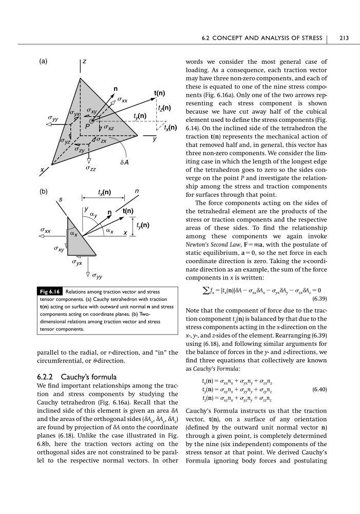
We find important relationships among the traction and stress components by studying the
Cauchy tetrahedron (Fig. 6.16a). Recall that the
inclined side of this element is given an area ␦A
and the areas of the orthogonal sides (␦A x , ␦A y , ␦A z )
are found by projection of ␦A onto the coordinate
planes (6.18). Unlike the case illustrated in Fig.
6.8b, here the traction vectors acting on the
orthogonal sides are not constrained to be parallel to the respective normal vectors. In other
words we consider the most general case of
loading. As a consequence, each traction vector
may have three non-zero components, and each of
these is equated to one of the nine stress components (Fig. 6.16a). Only one of the two arrows representing each stress component is shown
because we have cut away half of the cubical
element used to define the stress components (Fig.
6.14). On the inclined side of the tetrahedron the
traction t(n) represents the mechanical action of
that removed half and, in general, this vector has
three non-zero components. We consider the limiting case in which the length of the longest edge
of the tetrahedron goes to zero so the sides converge on the point P and investigate the relationship among the stress and traction components
for surfaces through that point.
The force components acting on the sides of
the tetrahedral element are the products of the
stress or traction components and the respective
areas of these sides. To find the relationship
among these components we again invoke
Newton’s Second Law, F ϭ ma, with the postulate of
static equilibrium, a ϭ 0, so the net force in each
coordinate direction is zero. Taking the x-coordinate direction as an example, the sum of the force
components in x is written:
(6.39)
Note that the component of force due to the traction component t x (n) is balanced by that due to the
stress components acting in the x-direction on the
x-, y-, and z-sides of the element. Rearranging (6.39)
using (6.18), and following similar arguments for
the balance of forces in the y- and z-directions, we
find three equations that collectively are known
as Cauchy’s Formula:
(6.40)
Cauchy’s Formula instructs us that the traction
vector, t(n), on a surface of any orientation
(defined by the outward unit normal vector n)
through a given point, is completely determined
by the nine (six independent) components of the
stress tensor at that point. We derived Cauchy’s
Formula ignoring body forces and postulating
t x (n) ϭ xx n x ϩ yx n y ϩ zx n z
t y (n) ϭ xy n x ϩ yy n y ϩ zy n z
t z (n) ϭ xz n x ϩ yz n y ϩ zz n z
͚ f x ϭ [t x (n)]␦A Ϫ xx ␦A x Ϫ yx ␦A y Ϫ zx ␦A z ϭ 0
6.2 CONCEPT AND ANALYSIS OF STRESS
213
Fig 6.16 Relations among traction vector and stress
tensor components. (a) Cauchy tetrahedron with traction
t(n) acting on surface with outward unit normal n and stress
components acting on coordinate planes. (b) Twodimensional relations among traction vector and stress
tensor components.
x
y
z
n
t(n)
dA
t x (n)
t y (n)
t z (n)
s xx
s zz
s yy
s yx
s zx
s yz
s zy
s xz
s xy
P
(a)
x
y
n
(b)
s xx
s xy
s yx
s yy
t x (n)
t y (n)
t(n)
␣ x
␣ x
␣ y
n
s
circumferential, or -direction.
6.2.2 Cauchy’s formula
We find important relationships among the traction and stress components by studying the
Cauchy tetrahedron (Fig. 6.16a). Recall that the
inclined side of this element is given an area ␦A
and the areas of the orthogonal sides (␦A x , ␦A y , ␦A z )
are found by projection of ␦A onto the coordinate
planes (6.18). Unlike the case illustrated in Fig.
6.8b, here the traction vectors acting on the
orthogonal sides are not constrained to be parallel to the respective normal vectors. In other
words we consider the most general case of
loading. As a consequence, each traction vector
may have three non-zero components, and each of
these is equated to one of the nine stress components (Fig. 6.16a). Only one of the two arrows representing each stress component is shown
because we have cut away half of the cubical
element used to define the stress components (Fig.
6.14). On the inclined side of the tetrahedron the
traction t(n) represents the mechanical action of
that removed half and, in general, this vector has
three non-zero components. We consider the limiting case in which the length of the longest edge
of the tetrahedron goes to zero so the sides converge on the point P and investigate the relationship among the stress and traction components
for surfaces through that point.
The force components acting on the sides of
the tetrahedral element are the products of the
stress or traction components and the respective
areas of these sides. To find the relationship
among these components we again invoke
Newton’s Second Law, F ϭ ma, with the postulate of
static equilibrium, a ϭ 0, so the net force in each
coordinate direction is zero. Taking the x-coordinate direction as an example, the sum of the force
components in x is written:
(6.39)
Note that the component of force due to the traction component t x (n) is balanced by that due to the
stress components acting in the x-direction on the
x-, y-, and z-sides of the element. Rearranging (6.39)
using (6.18), and following similar arguments for
the balance of forces in the y- and z-directions, we
find three equations that collectively are known
as Cauchy’s Formula:
(6.40)
Cauchy’s Formula instructs us that the traction
vector, t(n), on a surface of any orientation
(defined by the outward unit normal vector n)
through a given point, is completely determined
by the nine (six independent) components of the
stress tensor at that point. We derived Cauchy’s
Formula ignoring body forces and postulating
t x (n) ϭ xx n x ϩ yx n y ϩ zx n z
t y (n) ϭ xy n x ϩ yy n y ϩ zy n z
t z (n) ϭ xz n x ϩ yz n y ϩ zz n z
͚ f x ϭ [t x (n)]␦A Ϫ xx ␦A x Ϫ yx ␦A y Ϫ zx ␦A z ϭ 0
6.2 CONCEPT AND ANALYSIS OF STRESS
213
Fig 6.16 Relations among traction vector and stress
tensor components. (a) Cauchy tetrahedron with traction
t(n) acting on surface with outward unit normal n and stress
components acting on coordinate planes. (b) Twodimensional relations among traction vector and stress
tensor components.
x
y
z
n
t(n)
dA
t x (n)
t y (n)
t z (n)
s xx
s zz
s yy
s yx
s zx
s yz
s zy
s xz
s xy
P
(a)
x
y
n
(b)
s xx
s xy
s yx
s yy
t x (n)
t y (n)
t(n)
␣ x
␣ x
␣ y
n
s