

coordinate axes (x, y, z) may be replaced by (x 1 , x 2 ,
x 3 ) and the stress components are referred to in
aggregate as ij , where it is understood that the
ranges of the indices are i ϭ 1, 2, 3 and j ϭ 1, 2, 3.
The constraint on the shear stress components
(6.34) is expressed using indicial notation as:
(6.36)
This notation also facilitates the use of matrix
algebra because the subscripts for the stress components correspond to the row and column
numbers of the following matrix:
(6.37)
Recalling the “on–in” convention for subscripts
the first row contains the stress components
on the sides of the cubical element perpendicular
to the x 1 -axis and these components are directed,
respectively, in the x 1 -, x 2 -, and x 3 -directions.
Unlike the displacement, velocity, or acceleration the physical quantity we call the stress is not
defined at a point in the continuum by a single
vector with three components. In fact it takes six
traction vectors, three of which are independent
because of (6.9), acting on the orthogonal sides of
the cubical element to determine the nine stress
components. The state of stress at a point in the continuum is completely defined by the nine components of (6.35), six of which are independent
because of (6.34). Stress is referred to as a secondorder tensor to distinguish it from vectors, which are
first-order tensors, and scalars, which are zeroorder tensors. To complete the definition of stress
at a point, one would include the appropriate unit
of measure, along with the three coordinates of the
point. If the stress state is a function of time then
the definition would include the appropriate time.
We reduced the nine stress components to six
by postulating static equilibrium for the finite
cubical element, no body forces, and a homogeneous state of stress. In Chapter 7, after introducing the conservation laws, we show that (6.34)
is not so restricted, but applies to problems of fluid
dynamics in which elements experience both
linear and angular accelerations, to deformation
in the presence of body forces, and to heterogeneous stress states in solids and fluids. Here we
΄
11 12 13
21 22 23
31 32 33
΅
ij ϭ ji
also have ignored moments due to distributed
body or surface couples because most problems in
structural geology have found satisfactory correspondence to nature without invoking coupled
stresses (Malvern, 1969). The constraint on the
shear stress components (6.34) that leads to a symmetric matrix of stress components (6.35) is lost in
the presence of coupled stresses.
Some problems in structural geology can be
idealized using cylindrical symmetry about an
axis in three dimensions. The map view of the
dike pattern at Spanish Peaks is a possible
example (Fig. 6.12a) because the dikes appear to
radiate from a point near the center of West
Spanish Peak. A practical example would be the
cylindrical hole cut by a drilling rig to produce
water or hydrocarbons from porous formations at
depth. For these and other problems it is useful to
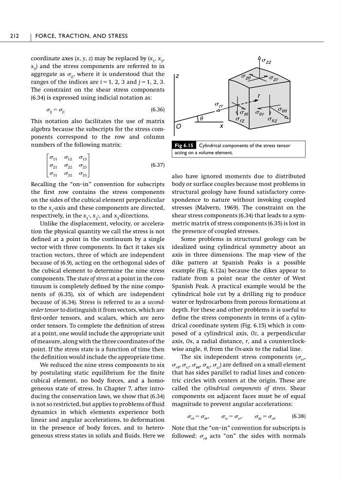
define the stress components in terms of a cylindrical coordinate system (Fig. 6.15) which is composed of a cylindrical axis, Oz, a perpendicular
axis, Ox, a radial distance, r, and a counterclockwise angle, , from the Ox-axis to the radial line.
The six independent stress components ( rr ,
r , rz , , z , zz ) are defined on a small element
that has sides parallel to radial lines and concentric circles with centers at the origin. These are
called the cylindrical components of stress. Shear
components on adjacent faces must be of equal
magnitude to prevent angular accelerations:
(6.38)
Note that the “on–in” convention for subscripts is
followed: r acts “on” the sides with normals
r ϭ r , rz ϭ zr , z ϭ z
212
FORCE, TRACTION, AND STRESS
Fig 6.15 Cylindrical components of the stress tensor
acting on a volume element.
s zz
z
u
r
s zu
s zr
s uz
s ur
s uu
s rr
s rz
s ru
x
O
x 3 ) and the stress components are referred to in
aggregate as ij , where it is understood that the
ranges of the indices are i ϭ 1, 2, 3 and j ϭ 1, 2, 3.
The constraint on the shear stress components
(6.34) is expressed using indicial notation as:
(6.36)
This notation also facilitates the use of matrix
algebra because the subscripts for the stress components correspond to the row and column
numbers of the following matrix:
(6.37)
Recalling the “on–in” convention for subscripts
the first row contains the stress components
on the sides of the cubical element perpendicular
to the x 1 -axis and these components are directed,
respectively, in the x 1 -, x 2 -, and x 3 -directions.
Unlike the displacement, velocity, or acceleration the physical quantity we call the stress is not
defined at a point in the continuum by a single
vector with three components. In fact it takes six
traction vectors, three of which are independent
because of (6.9), acting on the orthogonal sides of
the cubical element to determine the nine stress
components. The state of stress at a point in the continuum is completely defined by the nine components of (6.35), six of which are independent
because of (6.34). Stress is referred to as a secondorder tensor to distinguish it from vectors, which are
first-order tensors, and scalars, which are zeroorder tensors. To complete the definition of stress
at a point, one would include the appropriate unit
of measure, along with the three coordinates of the
point. If the stress state is a function of time then
the definition would include the appropriate time.
We reduced the nine stress components to six
by postulating static equilibrium for the finite
cubical element, no body forces, and a homogeneous state of stress. In Chapter 7, after introducing the conservation laws, we show that (6.34)
is not so restricted, but applies to problems of fluid
dynamics in which elements experience both
linear and angular accelerations, to deformation
in the presence of body forces, and to heterogeneous stress states in solids and fluids. Here we
΄
11 12 13
21 22 23
31 32 33
΅
ij ϭ ji
also have ignored moments due to distributed
body or surface couples because most problems in
structural geology have found satisfactory correspondence to nature without invoking coupled
stresses (Malvern, 1969). The constraint on the
shear stress components (6.34) that leads to a symmetric matrix of stress components (6.35) is lost in
the presence of coupled stresses.
Some problems in structural geology can be
idealized using cylindrical symmetry about an
axis in three dimensions. The map view of the
dike pattern at Spanish Peaks is a possible
example (Fig. 6.12a) because the dikes appear to
radiate from a point near the center of West
Spanish Peak. A practical example would be the
cylindrical hole cut by a drilling rig to produce
water or hydrocarbons from porous formations at
depth. For these and other problems it is useful to
define the stress components in terms of a cylindrical coordinate system (Fig. 6.15) which is composed of a cylindrical axis, Oz, a perpendicular
axis, Ox, a radial distance, r, and a counterclockwise angle, , from the Ox-axis to the radial line.
The six independent stress components ( rr ,
r , rz , , z , zz ) are defined on a small element
that has sides parallel to radial lines and concentric circles with centers at the origin. These are
called the cylindrical components of stress. Shear
components on adjacent faces must be of equal
magnitude to prevent angular accelerations:
(6.38)
Note that the “on–in” convention for subscripts is
followed: r acts “on” the sides with normals
r ϭ r , rz ϭ zr , z ϭ z
212
FORCE, TRACTION, AND STRESS
Fig 6.15 Cylindrical components of the stress tensor
acting on a volume element.
s zz
z
u
r
s zu
s zr
s uz
s ur
s uu
s rr
s rz
s ru
x
O