

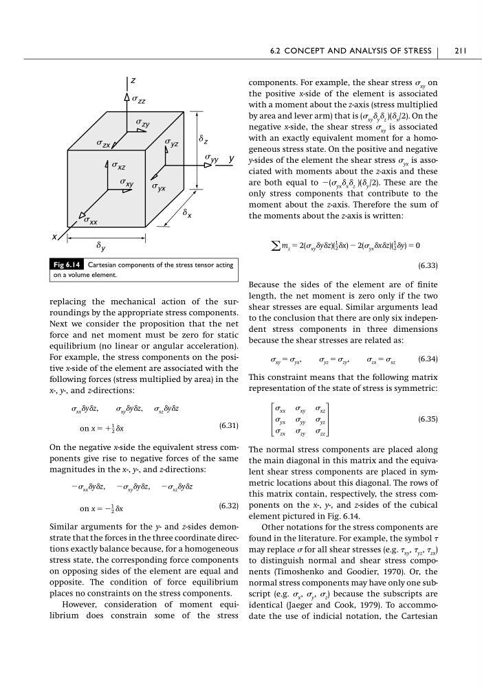
replacing the mechanical action of the surroundings by the appropriate stress components.
Next we consider the proposition that the net
force and net moment must be zero for static
equilibrium (no linear or angular acceleration).
For example, the stress components on the positive x-side of the element are associated with the
following forces (stress multiplied by area) in the
x-, y-, and z-directions:
(6.31)
On the negative x-side the equivalent stress components give rise to negative forces of the same
magnitudes in the x-, y-, and z-directions:
(6.32)
Similar arguments for the y- and z-sides demonstrate that the forces in the three coordinate directions exactly balance because, for a homogeneous
stress state, the corresponding force components
on opposing sides of the element are equal and
opposite. The condition of force equilibrium
places no constraints on the stress components.
However, consideration of moment equilibrium does constrain some of the stress
on x ϭ Ϫ
1
2 ␦x
Ϫ xx ␦y␦z, Ϫ xy ␦y␦z, Ϫ xz ␦y␦z
on x ϭ ϩ
1
2 ␦x
xx ␦y␦z, xy ␦y␦z, xz ␦y␦z
components. For example, the shear stress xy on
the positive x-side of the element is associated
with a moment about the z-axis (stress multiplied
by area and lever arm) that is ( xy ␦ y ␦ z )(␦ x /2). On the
negative x-side, the shear stress xy is associated
with an exactly equivalent moment for a homogeneous stress state. On the positive and negative
y-sides of the element the shear stress yx is associated with moments about the z-axis and these
are both equal to Ϫ( yx ␦ x ␦ z )(␦ y /2). These are the
only stress components that contribute to the
moment about the z-axis. Therefore the sum of
the moments about the z-axis is written:
(6.33)
Because the sides of the element are of finite
length, the net moment is zero only if the two
shear stresses are equal. Similar arguments lead
to the conclusion that there are only six independent stress components in three dimensions
because the shear stresses are related as:
(6.34)
This constraint means that the following matrix
representation of the state of stress is symmetric:
(6.35)
The normal stress components are placed along
the main diagonal in this matrix and the equivalent shear stress components are placed in symmetric locations about this diagonal. The rows of
this matrix contain, respectively, the stress components on the x-, y-, and z-sides of the cubical
element pictured in Fig. 6.14.
Other notations for the stress components are
found in the literature. For example, the symbol
may replace for all shear stresses (e.g. xy , yz , zx )
to distinguish normal and shear stress components (Timoshenko and Goodier, 1970). Or, the
normal stress components may have only one subscript (e.g. x , y , z ) because the subscripts are
identical (Jaeger and Cook, 1979). To accommodate the use of indicial notation, the Cartesian
΄
xx xy xz
yx yy yz
zx zy zz
΅
xy ϭ yx , yz ϭ zy , zx ϭ xz
͚ m z ϭ 2( xy ␦y␦z)(
1
2 ␦x) Ϫ 2( yx ␦x␦z)(
1
2 ␦y) ϭ 0
6.2 CONCEPT AND ANALYSIS OF STRESS
211
Fig 6.14 Cartesian components of the stress tensor acting
on a volume element.
x
z
y
s xx
s yx
s yz
s zx
s zy
s zz
s xz
s yy
s xy
d x
d z
d y
Next we consider the proposition that the net
force and net moment must be zero for static
equilibrium (no linear or angular acceleration).
For example, the stress components on the positive x-side of the element are associated with the
following forces (stress multiplied by area) in the
x-, y-, and z-directions:
(6.31)
On the negative x-side the equivalent stress components give rise to negative forces of the same
magnitudes in the x-, y-, and z-directions:
(6.32)
Similar arguments for the y- and z-sides demonstrate that the forces in the three coordinate directions exactly balance because, for a homogeneous
stress state, the corresponding force components
on opposing sides of the element are equal and
opposite. The condition of force equilibrium
places no constraints on the stress components.
However, consideration of moment equilibrium does constrain some of the stress
on x ϭ Ϫ
1
2 ␦x
Ϫ xx ␦y␦z, Ϫ xy ␦y␦z, Ϫ xz ␦y␦z
on x ϭ ϩ
1
2 ␦x
xx ␦y␦z, xy ␦y␦z, xz ␦y␦z
components. For example, the shear stress xy on
the positive x-side of the element is associated
with a moment about the z-axis (stress multiplied
by area and lever arm) that is ( xy ␦ y ␦ z )(␦ x /2). On the
negative x-side, the shear stress xy is associated
with an exactly equivalent moment for a homogeneous stress state. On the positive and negative
y-sides of the element the shear stress yx is associated with moments about the z-axis and these
are both equal to Ϫ( yx ␦ x ␦ z )(␦ y /2). These are the
only stress components that contribute to the
moment about the z-axis. Therefore the sum of
the moments about the z-axis is written:
(6.33)
Because the sides of the element are of finite
length, the net moment is zero only if the two
shear stresses are equal. Similar arguments lead
to the conclusion that there are only six independent stress components in three dimensions
because the shear stresses are related as:
(6.34)
This constraint means that the following matrix
representation of the state of stress is symmetric:
(6.35)
The normal stress components are placed along
the main diagonal in this matrix and the equivalent shear stress components are placed in symmetric locations about this diagonal. The rows of
this matrix contain, respectively, the stress components on the x-, y-, and z-sides of the cubical
element pictured in Fig. 6.14.
Other notations for the stress components are
found in the literature. For example, the symbol
may replace for all shear stresses (e.g. xy , yz , zx )
to distinguish normal and shear stress components (Timoshenko and Goodier, 1970). Or, the
normal stress components may have only one subscript (e.g. x , y , z ) because the subscripts are
identical (Jaeger and Cook, 1979). To accommodate the use of indicial notation, the Cartesian
΄
xx xy xz
yx yy yz
zx zy zz
΅
xy ϭ yx , yz ϭ zy , zx ϭ xz
͚ m z ϭ 2( xy ␦y␦z)(
1
2 ␦x) Ϫ 2( yx ␦x␦z)(
1
2 ␦y) ϭ 0
6.2 CONCEPT AND ANALYSIS OF STRESS
211
Fig 6.14 Cartesian components of the stress tensor acting
on a volume element.
x
z
y
s xx
s yx
s yz
s zx
s zy
s zz
s xz
s yy
s xy
d x
d z
d y