

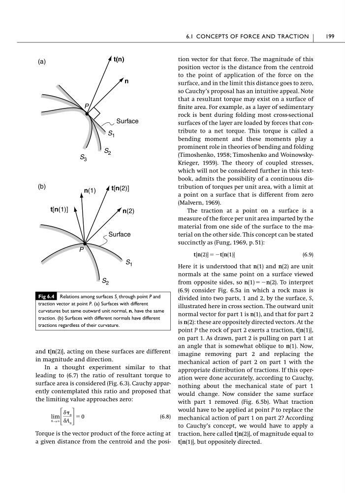
and t[n(2)], acting on these surfaces are different
in magnitude and direction.
In a thought experiment similar to that
leading to (6.7) the ratio of resultant torque to
surface area is considered (Fig. 6.3). Cauchy apparently contemplated this ratio and proposed that
the limiting value approaches zero:
(6.8)
Torque is the vector product of the force acting at
a given distance from the centroid and the posilim
n→ϱ ΄
␦ n
␦A n ΅
ϭ 0
tion vector for that force. The magnitude of this
position vector is the distance from the centroid
to the point of application of the force on the
surface, and in the limit this distance goes to zero,
so Cauchy’s proposal has an intuitive appeal. Note
that a resultant torque may exist on a surface of
finite area. For example, as a layer of sedimentary
rock is bent during folding most cross-sectional
surfaces of the layer are loaded by forces that contribute to a net torque. This torque is called a
bending moment and these moments play a
prominent role in theories of bending and folding
(Timoshenko, 1958; Timoshenko and WoinowskyKrieger, 1959). The theory of coupled stresses,
which will not be considered further in this textbook, admits the possibility of a continuous distribution of torques per unit area, with a limit at
a point on a surface that is different from zero
(Malvern, 1969).
The traction at a point on a surface is a
measure of the force per unit area imparted by the
material from one side of the surface to the material on the other side. This concept can be stated
succinctly as (Fung, 1969, p. 51):
(6.9)
Here it is understood that n(1) and n(2) are unit
normals at the same point on a surface viewed
from opposite sides, so n(1) ϭϪn(2). To interpret
(6.9) consider Fig. 6.5a in which a rock mass is
divided into two parts, 1 and 2, by the surface, S,
illustrated here in cross section. The outward unit
normal vector for part 1 is n(1), and that for part 2
is n(2): these are oppositely directed vectors. At the
point P the rock of part 2 exerts a traction, t[n(1)],
on part 1. As drawn, part 2 is pulling on part 1 at
an angle that is somewhat oblique to n(1). Now,
imagine removing part 2 and replacing the
mechanical action of part 2 on part 1 with the
appropriate distribution of tractions. If this operation were done accurately, according to Cauchy,
nothing about the mechanical state of part 1
would change. Now consider the same surface
with part 1 removed (Fig. 6.5b). What traction
would have to be applied at point P to replace the
mechanical action of part 1 on part 2? According
to Cauchy’s concept, we would have to apply a
traction, here called t[n(2)], of magnitude equal to
t[n(1)], but oppositely directed.
t[n(2)] ϭ Ϫt[n(1)]
6.1 CONCEPTS OF FORCE AND TRACTION
199
Fig 6.4 Relations among surfaces S i through point P and
traction vector at point P. (a) Surfaces with different
curvatures but same outward unit normal, n, have the same
traction. (b) Surfaces with different normals have different
tractions regardless of their curvature.
(a)
n
(b)
Surface
P
S 1
S 3
S 2
n(2)
Surface
P
S 1
S 2
n(1)
t[n(2)]
t[n(1)]
t(n)
in magnitude and direction.
In a thought experiment similar to that
leading to (6.7) the ratio of resultant torque to
surface area is considered (Fig. 6.3). Cauchy apparently contemplated this ratio and proposed that
the limiting value approaches zero:
(6.8)
Torque is the vector product of the force acting at
a given distance from the centroid and the posilim
n→ϱ ΄
␦ n
␦A n ΅
ϭ 0
tion vector for that force. The magnitude of this
position vector is the distance from the centroid
to the point of application of the force on the
surface, and in the limit this distance goes to zero,
so Cauchy’s proposal has an intuitive appeal. Note
that a resultant torque may exist on a surface of
finite area. For example, as a layer of sedimentary
rock is bent during folding most cross-sectional
surfaces of the layer are loaded by forces that contribute to a net torque. This torque is called a
bending moment and these moments play a
prominent role in theories of bending and folding
(Timoshenko, 1958; Timoshenko and WoinowskyKrieger, 1959). The theory of coupled stresses,
which will not be considered further in this textbook, admits the possibility of a continuous distribution of torques per unit area, with a limit at
a point on a surface that is different from zero
(Malvern, 1969).
The traction at a point on a surface is a
measure of the force per unit area imparted by the
material from one side of the surface to the material on the other side. This concept can be stated
succinctly as (Fung, 1969, p. 51):
(6.9)
Here it is understood that n(1) and n(2) are unit
normals at the same point on a surface viewed
from opposite sides, so n(1) ϭϪn(2). To interpret
(6.9) consider Fig. 6.5a in which a rock mass is
divided into two parts, 1 and 2, by the surface, S,
illustrated here in cross section. The outward unit
normal vector for part 1 is n(1), and that for part 2
is n(2): these are oppositely directed vectors. At the
point P the rock of part 2 exerts a traction, t[n(1)],
on part 1. As drawn, part 2 is pulling on part 1 at
an angle that is somewhat oblique to n(1). Now,
imagine removing part 2 and replacing the
mechanical action of part 2 on part 1 with the
appropriate distribution of tractions. If this operation were done accurately, according to Cauchy,
nothing about the mechanical state of part 1
would change. Now consider the same surface
with part 1 removed (Fig. 6.5b). What traction
would have to be applied at point P to replace the
mechanical action of part 1 on part 2? According
to Cauchy’s concept, we would have to apply a
traction, here called t[n(2)], of magnitude equal to
t[n(1)], but oppositely directed.
t[n(2)] ϭ Ϫt[n(1)]
6.1 CONCEPTS OF FORCE AND TRACTION
199
Fig 6.4 Relations among surfaces S i through point P and
traction vector at point P. (a) Surfaces with different
curvatures but same outward unit normal, n, have the same
traction. (b) Surfaces with different normals have different
tractions regardless of their curvature.
(a)
n
(b)
Surface
P
S 1
S 3
S 2
n(2)
Surface
P
S 1
S 2
n(1)
t[n(2)]
t[n(1)]
t(n)