

model, the gaps opened up at the broken hinges
are exactly compensated by interpenetrations
between layers. If, instead of physically impossible
interpenetration, the layer ends are dissolved and
the material deposited in the gaps, both processes
allowed by the presence of pore water and the
slowness of the folding process, structures somewhat like the “saddle reefs” seen in the fold in Fig.
5.16 are produced. De Sitter’s aim in “breaking”
the layers was to produce gaps of this sort.
However, he “backed the layers away,” so that they
only touched at single points, there was no interpenetration, and the gaps were larger.
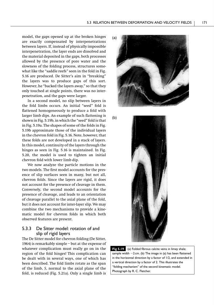
In a second model, no slip between layers in
the fold limbs occurs. An initial “seed” fold is
flattened homogeneously to produce a fold with
larger limb dips. An example of such flattening is
shown in Fig. 5.19b, in which the “seed” fold is that
in Fig. 5.19a. The shapes of some of the folds in Fig.
5.19b approximate those of the individual layers
in the chevron fold in Fig. 5.16. Note, however, that
these folds are not developed in a stack of layers.
In this model, continuity of the layers through the
hinges as seen in Fig. 5.16 is maintained. In Fig.
5.20, the model is used to tighten an initial
chevron fold with lower limb dip.
We now analyze the particle motions in the
two models. The first model accounts for the presence of slip surfaces seen in many, but not all,
chevron folds. Since the layers are rigid, it does
not account for the presence of cleavage in them.
Conversely, the second model accounts for the
presence of cleavage, and leads to an orientation
of cleavage parallel to the axial plane of the fold,
but it does not account for inter-layer slip. We may
combine the two mechanisms to provide a kinematic model for chevron folds in which both
observed features are present.
5.3.3 De Sitter model: rotation of and
slip of rigid layers
The De Sitter model for chevron folding (De Sitter,
1964) is remarkably simple – but at the expense of
whatever complication must really go on in the
region of the fold hinges! This complication can
be dealt with in several ways, one of which has
been described. The fold limbs rotate as the span
of the limb, S, normal to the axial plane of the
fold, is reduced (Fig. 5.21a). Only a single limb is
5.3 RELATION BETWEEN DEFORMATION AND VELOCITY FIELDS
171
Fig 5.19 (a) Folded fibrous calcite veins in limey shale;
sample width ϳ2 cm. (b) The image in (a) has been flattened
in the horizontal direction by a factor of 1/2, and extended in
a vertical direction by a factor of 2. This illustrates the
“folding mechanism” of the second kinematic model.
Photograph by R. C. Fletcher.
(a)
(b)
are exactly compensated by interpenetrations
between layers. If, instead of physically impossible
interpenetration, the layer ends are dissolved and
the material deposited in the gaps, both processes
allowed by the presence of pore water and the
slowness of the folding process, structures somewhat like the “saddle reefs” seen in the fold in Fig.
5.16 are produced. De Sitter’s aim in “breaking”
the layers was to produce gaps of this sort.
However, he “backed the layers away,” so that they
only touched at single points, there was no interpenetration, and the gaps were larger.
In a second model, no slip between layers in
the fold limbs occurs. An initial “seed” fold is
flattened homogeneously to produce a fold with
larger limb dips. An example of such flattening is
shown in Fig. 5.19b, in which the “seed” fold is that
in Fig. 5.19a. The shapes of some of the folds in Fig.
5.19b approximate those of the individual layers
in the chevron fold in Fig. 5.16. Note, however, that
these folds are not developed in a stack of layers.
In this model, continuity of the layers through the
hinges as seen in Fig. 5.16 is maintained. In Fig.
5.20, the model is used to tighten an initial
chevron fold with lower limb dip.
We now analyze the particle motions in the
two models. The first model accounts for the presence of slip surfaces seen in many, but not all,
chevron folds. Since the layers are rigid, it does
not account for the presence of cleavage in them.
Conversely, the second model accounts for the
presence of cleavage, and leads to an orientation
of cleavage parallel to the axial plane of the fold,
but it does not account for inter-layer slip. We may
combine the two mechanisms to provide a kinematic model for chevron folds in which both
observed features are present.
5.3.3 De Sitter model: rotation of and
slip of rigid layers
The De Sitter model for chevron folding (De Sitter,
1964) is remarkably simple – but at the expense of
whatever complication must really go on in the
region of the fold hinges! This complication can
be dealt with in several ways, one of which has
been described. The fold limbs rotate as the span
of the limb, S, normal to the axial plane of the
fold, is reduced (Fig. 5.21a). Only a single limb is
5.3 RELATION BETWEEN DEFORMATION AND VELOCITY FIELDS
171
Fig 5.19 (a) Folded fibrous calcite veins in limey shale;
sample width ϳ2 cm. (b) The image in (a) has been flattened
in the horizontal direction by a factor of 1/2, and extended in
a vertical direction by a factor of 2. This illustrates the
“folding mechanism” of the second kinematic model.
Photograph by R. C. Fletcher.
(a)
(b)