

at the contact, we use a method similar to that
used to find the ratio of deformed ellipsoid axes in
the spherical shell model.
Consider a pill-shaped element of material
whose upper surface coincides with the surface of
the sphere at its apex. The element is taken to be
sufficiently small that the surface of the intrusion
is approximated by the horizontal tangent plane.
In the initial state, before any rise of the sphere,
the radius of the pill is ␦Y and its thickness is ␦X.
The volume of the pill is ␦V ϭ (␦Y )
2 ␦X. After some
amount of rise, in the final state, the radius and
thickness of the pill are ␦y and ␦x, and its volume
is ␦v ϭ (␦y)
2 ␦x. Since the volumes are equal, ␦y/␦Y
ϭ (␦x/␦X)
1/2 . The final form of the pill may be
found by tracking the position of the particle with
initial position (R, ␦Y ) on the tangent plane, or
with initial position (R Ϫ ␦X, 0) on the vertical axis
of the sphere. For the former, the velocity away
from the center point is:
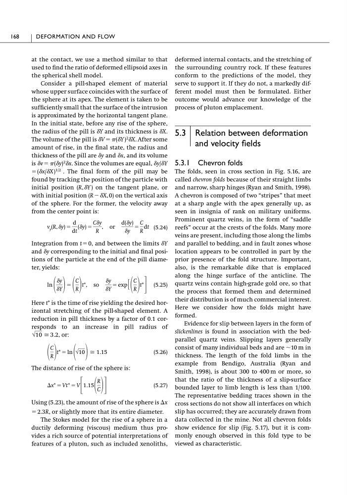
(5.24)
Integration from tϭ0, and between the limits ␦Y
and ␦y corresponding to the initial and final positions of the particle at the end of the pill diameter, yields:
(5.25)
Here t* is the time of rise yielding the desired horizontal stretching of the pill-shaped element. A
reduction in pill thickness by a factor of 0.1 corresponds to an increase in pill radius of
(5.26)
The distance of rise of the sphere is:
(5.27)
Using (5.23), the amount of rise of the sphere is
ϭ 2.3R, or slightly more that its entire diameter.
The Stokes model for the rise of a sphere in a
ductily deforming (viscous) medium thus provides a rich source of potential interpretations of
features of a pluton, such as included xenoliths,
⌬x
⌬x* ϭ Vt* ϭ V ΄ 1.15
R
C ΅
C
R t* ϭ ln √10 Х 1.15
√10 Х 3.2, or:
ln
␦y
␦Y
ϭ
C
R
t*, so
␦y
␦Y
ϭ exp ΄
C
R
t*
΅
v y (R, ␦y) ϭ
d
dt
(␦y) ϭ
C␦y
R
, or
d(␦y)
␦y
ϭ
C
R
dt
deformed internal contacts, and the stretching of
the surrounding country rock. If these features
conform to the predictions of the model, they
serve to support it. If they do not, a markedly different model must then be formulated. Either
outcome would advance our knowledge of the
process of pluton emplacement.
5.3 Relation between deformation
and velocity fields
5.3.1 Chevron folds
The folds, seen in cross section in Fig. 5.16, are
called chevron folds because of their straight limbs
and narrow, sharp hinges (Ryan and Smith, 1998).
A chevron is composed of two “stripes” that meet
at a sharp angle with the apex generally up, as
seen in insignia of rank on military uniforms.
Prominent quartz veins, in the form of “saddle
reefs” occur at the crests of the folds. Many more
veins are present, including those along the limbs
and parallel to bedding, and in fault zones whose
location appears to be controlled in part by the
prior presence of the fold structure. Important,
also, is the remarkable dike that is emplaced
along the hinge surface of the anticline. The
quartz veins contain high-grade gold ore, so that
the process that formed them and determined
their distribution is of much commercial interest.
Here we consider how the folds might have
formed.
Evidence for slip between layers in the form of
slickenlines is found in association with the bedparallel quartz veins. Slipping layers generally
consist of many individual beds and are ϳ10 m in
thickness. The length of the fold limbs in the
example from Bendigo, Australia (Ryan and
Smith, 1998), is about 300 to 400 m or more, so
that the ratio of the thickness of a slip-surface
bounded layer to limb length is less than 1/100.
The representative bedding traces shown in the
cross sections do not show all interfaces on which
slip has occurred; they are accurately drawn from
data collected in the mine. Not all chevron folds
show evidence for slip (Fig. 5.17), but it is commonly enough observed in this fold type to be
viewed as characteristic.
168
DEFORMATION AND FLOW
used to find the ratio of deformed ellipsoid axes in
the spherical shell model.
Consider a pill-shaped element of material
whose upper surface coincides with the surface of
the sphere at its apex. The element is taken to be
sufficiently small that the surface of the intrusion
is approximated by the horizontal tangent plane.
In the initial state, before any rise of the sphere,
the radius of the pill is ␦Y and its thickness is ␦X.
The volume of the pill is ␦V ϭ (␦Y )
2 ␦X. After some
amount of rise, in the final state, the radius and
thickness of the pill are ␦y and ␦x, and its volume
is ␦v ϭ (␦y)
2 ␦x. Since the volumes are equal, ␦y/␦Y
ϭ (␦x/␦X)
1/2 . The final form of the pill may be
found by tracking the position of the particle with
initial position (R, ␦Y ) on the tangent plane, or
with initial position (R Ϫ ␦X, 0) on the vertical axis
of the sphere. For the former, the velocity away
from the center point is:
(5.24)
Integration from tϭ0, and between the limits ␦Y
and ␦y corresponding to the initial and final positions of the particle at the end of the pill diameter, yields:
(5.25)
Here t* is the time of rise yielding the desired horizontal stretching of the pill-shaped element. A
reduction in pill thickness by a factor of 0.1 corresponds to an increase in pill radius of
(5.26)
The distance of rise of the sphere is:
(5.27)
Using (5.23), the amount of rise of the sphere is
ϭ 2.3R, or slightly more that its entire diameter.
The Stokes model for the rise of a sphere in a
ductily deforming (viscous) medium thus provides a rich source of potential interpretations of
features of a pluton, such as included xenoliths,
⌬x
⌬x* ϭ Vt* ϭ V ΄ 1.15
R
C ΅
C
R t* ϭ ln √10 Х 1.15
√10 Х 3.2, or:
ln
␦y
␦Y
ϭ
C
R
t*, so
␦y
␦Y
ϭ exp ΄
C
R
t*
΅
v y (R, ␦y) ϭ
d
dt
(␦y) ϭ
C␦y
R
, or
d(␦y)
␦y
ϭ
C
R
dt
deformed internal contacts, and the stretching of
the surrounding country rock. If these features
conform to the predictions of the model, they
serve to support it. If they do not, a markedly different model must then be formulated. Either
outcome would advance our knowledge of the
process of pluton emplacement.
5.3 Relation between deformation
and velocity fields
5.3.1 Chevron folds
The folds, seen in cross section in Fig. 5.16, are
called chevron folds because of their straight limbs
and narrow, sharp hinges (Ryan and Smith, 1998).
A chevron is composed of two “stripes” that meet
at a sharp angle with the apex generally up, as
seen in insignia of rank on military uniforms.
Prominent quartz veins, in the form of “saddle
reefs” occur at the crests of the folds. Many more
veins are present, including those along the limbs
and parallel to bedding, and in fault zones whose
location appears to be controlled in part by the
prior presence of the fold structure. Important,
also, is the remarkable dike that is emplaced
along the hinge surface of the anticline. The
quartz veins contain high-grade gold ore, so that
the process that formed them and determined
their distribution is of much commercial interest.
Here we consider how the folds might have
formed.
Evidence for slip between layers in the form of
slickenlines is found in association with the bedparallel quartz veins. Slipping layers generally
consist of many individual beds and are ϳ10 m in
thickness. The length of the fold limbs in the
example from Bendigo, Australia (Ryan and
Smith, 1998), is about 300 to 400 m or more, so
that the ratio of the thickness of a slip-surface
bounded layer to limb length is less than 1/100.
The representative bedding traces shown in the
cross sections do not show all interfaces on which
slip has occurred; they are accurately drawn from
data collected in the mine. Not all chevron folds
show evidence for slip (Fig. 5.17), but it is commonly enough observed in this fold type to be
viewed as characteristic.
168
DEFORMATION AND FLOW