

hemispherical volume, and a scheme adapted to a
rising sub-spherical intrusion might be worked
out. In any case, the more elaborate model should
follow Stokes’ example and use a complete
mechanics.
Thinning of the “wall rock” at the top of the
sphere can be determined from the Stokes model.
A boundary condition was imposed in the model
that required the fluids to stick at their interface.
Thus, the stretching of a thin layer at the margin
of the “intrusion” must be the same as that of a
thin layer in the adjacent “wall rock.” The thinning shown by the deformed initial spheres near
the surface must substantially under-estimate the
thinning at the contact with the overlying fluid
medium, since a large fraction of this has been
greatly thinned to make room for the material
represented by the grid. To estimate the thinning
5.2 KINEMATIC MODELS, VELOCITY MODELS, AND DEFORMATION
167
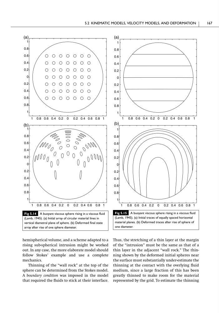
Fig 5.14 A buoyant viscous sphere rising in a viscous fluid
(Lamb, 1945). (a) Initial array of circular material lines in
vertical diametral plane of sphere. (b) Deformed final state
array after rise of one sphere diameter.
1
0.8
0.6
0.4
0.2
0
0.2
0.4
0.6
0.8
1
1 0.8 0.6 0.4 0.2 0 0.2 0.4 0.6 0.8 1
1
0.8
0.6
0.4
0.2
0
0.2
0.4
0.6
0.8
1
1 0.8 0.6 0.4 0.2 0 0.2 0.4 0.6 0.8 1
(a)
(b)
Fig 5.15 A buoyant viscous sphere rising in a viscous fluid
(Lamb, 1945). (a) Initial traces of equally spaced horizontal
material planes. (b) Deformed traces after rise of sphere of
one diameter.
1
0.8
0.6
0.4
0.2
0
0.2
0.4
0.6
0.8
1
1 0.8 0.6 0.4 0.2 0 0.2 0.4 0.6 0.8 1
1
0.8
0.6
0.4
0.2
0
0.2
0.4
0.6
0.8
1
1 0.8 0.6 0.4 0.2 0 0.2 0.4 0.6 0.8 1
(a)
(b)
rising sub-spherical intrusion might be worked
out. In any case, the more elaborate model should
follow Stokes’ example and use a complete
mechanics.
Thinning of the “wall rock” at the top of the
sphere can be determined from the Stokes model.
A boundary condition was imposed in the model
that required the fluids to stick at their interface.
Thus, the stretching of a thin layer at the margin
of the “intrusion” must be the same as that of a
thin layer in the adjacent “wall rock.” The thinning shown by the deformed initial spheres near
the surface must substantially under-estimate the
thinning at the contact with the overlying fluid
medium, since a large fraction of this has been
greatly thinned to make room for the material
represented by the grid. To estimate the thinning
5.2 KINEMATIC MODELS, VELOCITY MODELS, AND DEFORMATION
167
Fig 5.14 A buoyant viscous sphere rising in a viscous fluid
(Lamb, 1945). (a) Initial array of circular material lines in
vertical diametral plane of sphere. (b) Deformed final state
array after rise of one sphere diameter.
1
0.8
0.6
0.4
0.2
0
0.2
0.4
0.6
0.8
1
1 0.8 0.6 0.4 0.2 0 0.2 0.4 0.6 0.8 1
1
0.8
0.6
0.4
0.2
0
0.2
0.4
0.6
0.8
1
1 0.8 0.6 0.4 0.2 0 0.2 0.4 0.6 0.8 1
(a)
(b)
Fig 5.15 A buoyant viscous sphere rising in a viscous fluid
(Lamb, 1945). (a) Initial traces of equally spaced horizontal
material planes. (b) Deformed traces after rise of sphere of
one diameter.
1
0.8
0.6
0.4
0.2
0
0.2
0.4
0.6
0.8
1
1 0.8 0.6 0.4 0.2 0 0.2 0.4 0.6 0.8 1
1
0.8
0.6
0.4
0.2
0
0.2
0.4
0.6
0.8
1
1 0.8 0.6 0.4 0.2 0 0.2 0.4 0.6 0.8 1
(a)
(b)