

occupied position with coordinates X and Y at
time t ϭ 0:
(5.21)
The position at a small increment of time later
is:
(5.22)
For certain motions, possibly even in the present
case, this equation, or its equivalent, may be integrated in closed form. Here, however, we assign
a small but finite value, advance the particle to its
new position, and repeat this process many times
to achieve the desired result.
It is most convenient to refer the interval
between initial and final states to the amount of
rise of the sphere, expressed in units of its radius,
R. The amount of rise is Vt, but from (5.16) and
(5.19):
(5.23)
The intrusion viscosity, 1 , is much less than that
of the country rock, . Time will be expressed in
units such that we may set Cϭ1 in (5.19). In unit
time, the sphere will rise by an amount equal to
its diameter, 2R.
Figure 5.13 shows the deformed state of a grid
whose intersection points correspond to the final
positions of a set of particles that initially lay at
the intersection points of the square grid in the
figure after a rise of one sphere radius. The
deformed grid lines are constructed by connecting grid points with straight segments. To a good
approximation, the line segments in the final
state correspond to the material lines connecting
grid points in the initial state, because the grid
elements are small enough.
As another example, Fig. 5.14b shows the final
positions and forms of an array of material circles
in the initial state (Fig. 5.14a) after rise of one
sphere diameter. The circles may be interpreted
as sections of initially spherical surfaces.
Provided an initial circle is infinitesimally small,
V
C
ϭ
2( ϩ 1 )
Х 2
⌬t
ϩ v y [x(t; X, Y ), y(t; X, Y)]⌬t
ϭ y(t; X, Y )
y(t ϩ ⌬t; X, Y )
ϩ v x [x(t; X, Y ), y(t; X, Y)]⌬t
ϭ x(t; X, Y )
x(t ϩ ⌬t; X, Y)
⌬t
y(0; X, Y ) ϭ Y
x(0; X, Y ) ϭ X
the three-dimensional surface in the deformed
state is an ellipsoid. The sections look only
approximately like ellipses because of their large
size. The distribution of deformation, with more
flattened forms outward and with long dimensions concentrically oriented is similar to that of
deformed xenoliths in the Chindamora pluton
(Fig. 5.9) or the model for it (Fig. 5.10b).
This result suggests that the rising sphere
model might provide an alternative to the
inflating intrusion model. However, this would
not seem to be supported by the roughly concentric pattern of intrusive rock types in that pluton.
In this model, a concentric pattern can be produced. Consider a set of equally spaced horizontal
surfaces in the initial state (Fig. 5.15a). After a rise
equal to the sphere diameter, these surfaces are
deformed into those shown in Fig. 5.15b. The
entire surfaces are formed by spinning this section
around the vertical axis. If the magma body had
developed a layered compositional sequence prior
to its rise, then something resembling a concentric distribution of magma types might arise. The
process of multiple injection proposed by Ramsay
is supported by his observations. It is not clear,
however, that multiple injection occurs by intrusion into the center of an expanding spherical or
166
DEFORMATION AND FLOW
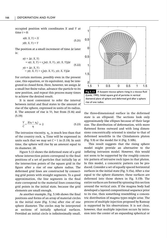
Fig 5.13 A buoyant viscous sphere rising in a viscous fluid
(Lamb, 1945). Initial square grid of particles in vertical
diametral plane of sphere and deformed grid after a sphere
rise of one radius.
1
0.5
0
0.5
1
1.5
2
1.5
1
0.5
0
0.5
1
1.5
time t ϭ 0:
(5.21)
The position at a small increment of time later
is:
(5.22)
For certain motions, possibly even in the present
case, this equation, or its equivalent, may be integrated in closed form. Here, however, we assign
a small but finite value, advance the particle to its
new position, and repeat this process many times
to achieve the desired result.
It is most convenient to refer the interval
between initial and final states to the amount of
rise of the sphere, expressed in units of its radius,
R. The amount of rise is Vt, but from (5.16) and
(5.19):
(5.23)
The intrusion viscosity, 1 , is much less than that
of the country rock, . Time will be expressed in
units such that we may set Cϭ1 in (5.19). In unit
time, the sphere will rise by an amount equal to
its diameter, 2R.
Figure 5.13 shows the deformed state of a grid
whose intersection points correspond to the final
positions of a set of particles that initially lay at
the intersection points of the square grid in the
figure after a rise of one sphere radius. The
deformed grid lines are constructed by connecting grid points with straight segments. To a good
approximation, the line segments in the final
state correspond to the material lines connecting
grid points in the initial state, because the grid
elements are small enough.
As another example, Fig. 5.14b shows the final
positions and forms of an array of material circles
in the initial state (Fig. 5.14a) after rise of one
sphere diameter. The circles may be interpreted
as sections of initially spherical surfaces.
Provided an initial circle is infinitesimally small,
V
C
ϭ
2( ϩ 1 )
Х 2
⌬t
ϩ v y [x(t; X, Y ), y(t; X, Y)]⌬t
ϭ y(t; X, Y )
y(t ϩ ⌬t; X, Y )
ϩ v x [x(t; X, Y ), y(t; X, Y)]⌬t
ϭ x(t; X, Y )
x(t ϩ ⌬t; X, Y)
⌬t
y(0; X, Y ) ϭ Y
x(0; X, Y ) ϭ X
the three-dimensional surface in the deformed
state is an ellipsoid. The sections look only
approximately like ellipses because of their large
size. The distribution of deformation, with more
flattened forms outward and with long dimensions concentrically oriented is similar to that of
deformed xenoliths in the Chindamora pluton
(Fig. 5.9) or the model for it (Fig. 5.10b).
This result suggests that the rising sphere
model might provide an alternative to the
inflating intrusion model. However, this would
not seem to be supported by the roughly concentric pattern of intrusive rock types in that pluton.
In this model, a concentric pattern can be produced. Consider a set of equally spaced horizontal
surfaces in the initial state (Fig. 5.15a). After a rise
equal to the sphere diameter, these surfaces are
deformed into those shown in Fig. 5.15b. The
entire surfaces are formed by spinning this section
around the vertical axis. If the magma body had
developed a layered compositional sequence prior
to its rise, then something resembling a concentric distribution of magma types might arise. The
process of multiple injection proposed by Ramsay
is supported by his observations. It is not clear,
however, that multiple injection occurs by intrusion into the center of an expanding spherical or
166
DEFORMATION AND FLOW
Fig 5.13 A buoyant viscous sphere rising in a viscous fluid
(Lamb, 1945). Initial square grid of particles in vertical
diametral plane of sphere and deformed grid after a sphere
rise of one radius.
1
0.5
0
0.5
1
1.5
2
1.5
1
0.5
0
0.5
1
1.5