

The inner integral is evaluated using (Selby, 1975,
p. 424):
(3.101)
The area of the helicoidal fracture surface is:
(3.102)
As the spatial rate of twist goes to zero, 1/c → 0, the
area goes to that of a rectangular plane, A → A 0 .
For unit half-width (b ϭ 1) and unit length (c ϭ 1),
we have A 0 ϭ 2, and the normalized area, A/A 0 ,
increases slowly and non-linearly with rate of
twist.
Using the dimensionless ratio b/c in (3.102), the
area of the helicoidal fracture surface takes the
form (Pollard et al., 2004):
(3.103)
This relationship demonstrates that the surface
area of n helicoidal fractures, each of half-width
b and length c, is less than the surface area of
a single helicoidal fracture of half-width nb and
A ϭ c 2
΄
b
c √
b
c
2
ϩ 1 ϩ ln
b
c
ϩ
√
b
c
2
ϩ 1
΅
A ϭ ΄ b √b 2 ϩ c 2 ϩ c 2 ln
b ϩ √b 2 ϩ c 2
c
΅
͵ √a 2 ϩ x 2 dx ϭ
1
2 ΄
x√a 2 ϩ x 2 ϩ a 2 ln (x ϩ √a 2 ϩ x 2 )
΅
length c. Taking the n fractures as a model for
the twist hackle in the fringe region of a joint
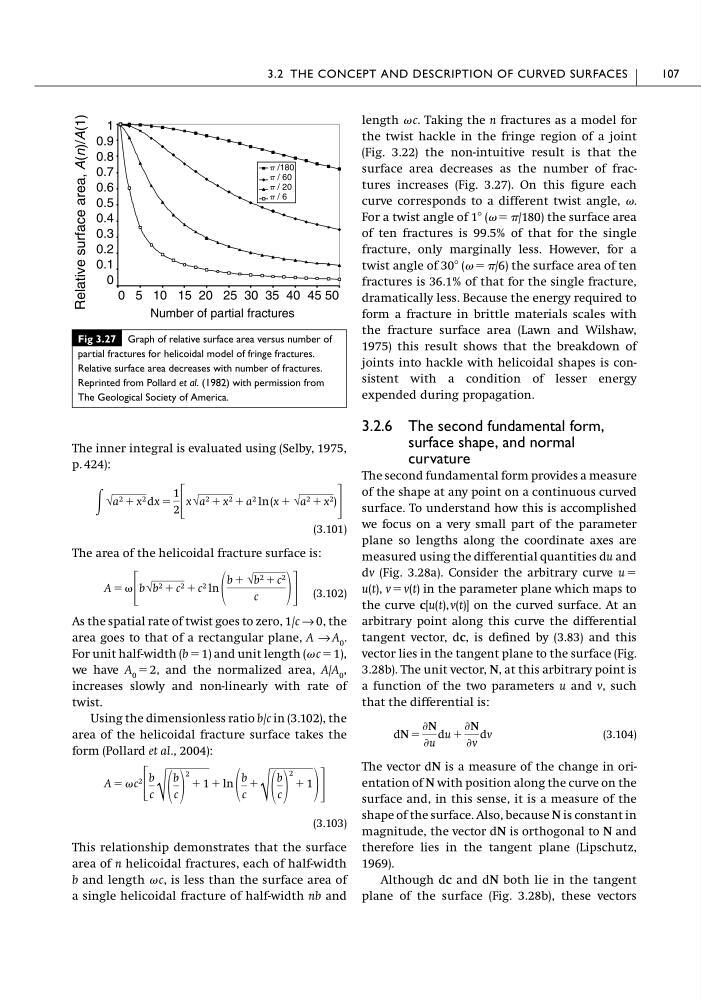
(Fig. 3.22) the non-intuitive result is that the
surface area decreases as the number of fractures increases (Fig. 3.27). On this figure each
curve corresponds to a different twist angle, .
For a twist angle of 1Њ ( ϭ /180) the surface area
of ten fractures is 99.5% of that for the single
fracture, only marginally less. However, for a
twist angle of 30Њ ( ϭ /6) the surface area of ten
fractures is 36.1% of that for the single fracture,
dramatically less. Because the energy required to
form a fracture in brittle materials scales with
the fracture surface area (Lawn and Wilshaw,
1975) this result shows that the breakdown of
joints into hackle with helicoidal shapes is consistent with a condition of lesser energy
expended during propagation.
3.2.6 The second fundamental form,
surface shape, and normal
curvature
The second fundamental form provides a measure
of the shape at any point on a continuous curved
surface. To understand how this is accomplished
we focus on a very small part of the parameter
plane so lengths along the coordinate axes are
measured using the differential quantities du and
dv (Fig. 3.28a). Consider the arbitrary curve u ϭ
u(t), v ϭ v(t) in the parameter plane which maps to
the curve c[u(t), v(t)] on the curved surface. At an
arbitrary point along this curve the differential
tangent vector, dc, is defined by (3.83) and this
vector lies in the tangent plane to the surface (Fig.
3.28b). The unit vector, N, at this arbitrary point is
a function of the two parameters u and v, such
that the differential is:
(3.104)
The vector dN is a measure of the change in orientation of N with position along the curve on the
surface and, in this sense, it is a measure of the
shape of the surface. Also, because N is constant in
magnitude, the vector dN is orthogonal to N and
therefore lies in the tangent plane (Lipschutz,
1969).
Although dc and dN both lie in the tangent
plane of the surface (Fig. 3.28b), these vectors
dN ϭ
ѨN
Ѩu
du ϩ
ѨN
Ѩv
dv
3.2 THE CONCEPT AND DESCRIPTION OF CURVED SURFACES
107
Number of partial fractures
Relative surface area, A(n)/A(1)
p /180
p / 60
p / 20
p / 6
0 5 10 15 20 25 30 35 40 45 50
1
0.9
0.8
0.7
0.6
0.5
0.4
0.3
0.2
0.1
0
Fig 3.27 Graph of relative surface area versus number of
partial fractures for helicoidal model of fringe fractures.
Relative surface area decreases with number of fractures.
Reprinted from Pollard et al. (1982) with permission from
The Geological Society of America.
p. 424):
(3.101)
The area of the helicoidal fracture surface is:
(3.102)
As the spatial rate of twist goes to zero, 1/c → 0, the
area goes to that of a rectangular plane, A → A 0 .
For unit half-width (b ϭ 1) and unit length (c ϭ 1),
we have A 0 ϭ 2, and the normalized area, A/A 0 ,
increases slowly and non-linearly with rate of
twist.
Using the dimensionless ratio b/c in (3.102), the
area of the helicoidal fracture surface takes the
form (Pollard et al., 2004):
(3.103)
This relationship demonstrates that the surface
area of n helicoidal fractures, each of half-width
b and length c, is less than the surface area of
a single helicoidal fracture of half-width nb and
A ϭ c 2
΄
b
c √
b
c
2
ϩ 1 ϩ ln
b
c
ϩ
√
b
c
2
ϩ 1
΅
A ϭ ΄ b √b 2 ϩ c 2 ϩ c 2 ln
b ϩ √b 2 ϩ c 2
c
΅
͵ √a 2 ϩ x 2 dx ϭ
1
2 ΄
x√a 2 ϩ x 2 ϩ a 2 ln (x ϩ √a 2 ϩ x 2 )
΅
length c. Taking the n fractures as a model for
the twist hackle in the fringe region of a joint
(Fig. 3.22) the non-intuitive result is that the
surface area decreases as the number of fractures increases (Fig. 3.27). On this figure each
curve corresponds to a different twist angle, .
For a twist angle of 1Њ ( ϭ /180) the surface area
of ten fractures is 99.5% of that for the single
fracture, only marginally less. However, for a
twist angle of 30Њ ( ϭ /6) the surface area of ten
fractures is 36.1% of that for the single fracture,
dramatically less. Because the energy required to
form a fracture in brittle materials scales with
the fracture surface area (Lawn and Wilshaw,
1975) this result shows that the breakdown of
joints into hackle with helicoidal shapes is consistent with a condition of lesser energy
expended during propagation.
3.2.6 The second fundamental form,
surface shape, and normal
curvature
The second fundamental form provides a measure
of the shape at any point on a continuous curved
surface. To understand how this is accomplished
we focus on a very small part of the parameter
plane so lengths along the coordinate axes are
measured using the differential quantities du and
dv (Fig. 3.28a). Consider the arbitrary curve u ϭ
u(t), v ϭ v(t) in the parameter plane which maps to
the curve c[u(t), v(t)] on the curved surface. At an
arbitrary point along this curve the differential
tangent vector, dc, is defined by (3.83) and this
vector lies in the tangent plane to the surface (Fig.
3.28b). The unit vector, N, at this arbitrary point is
a function of the two parameters u and v, such
that the differential is:
(3.104)
The vector dN is a measure of the change in orientation of N with position along the curve on the
surface and, in this sense, it is a measure of the
shape of the surface. Also, because N is constant in
magnitude, the vector dN is orthogonal to N and
therefore lies in the tangent plane (Lipschutz,
1969).
Although dc and dN both lie in the tangent
plane of the surface (Fig. 3.28b), these vectors
dN ϭ
ѨN
Ѩu
du ϩ
ѨN
Ѩv
dv
3.2 THE CONCEPT AND DESCRIPTION OF CURVED SURFACES
107
Number of partial fractures
Relative surface area, A(n)/A(1)
p /180
p / 60
p / 20
p / 6
0 5 10 15 20 25 30 35 40 45 50
1
0.9
0.8
0.7
0.6
0.5
0.4
0.3
0.2
0.1
0
Fig 3.27 Graph of relative surface area versus number of
partial fractures for helicoidal model of fringe fractures.
Relative surface area decreases with number of fractures.
Reprinted from Pollard et al. (1982) with permission from
The Geological Society of America.