

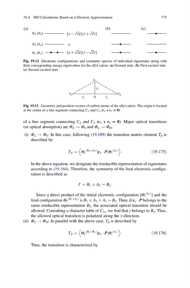
of a line segment connecting C 2 and C 3 (r 2 + r 3 = 0). Major optical transitions
(or optical absorption) are Φ L ! Φ 0 and Φ L ! Φ H .
(i) Φ L ! Φ 0 : In this case, following (19.109) the transition matrix element T fi is
described by
T fi ¼ Θ f
B 1 ÂA 2
ð
Þ
jε e Á PjΘ i
A 1
ð Þ
D
E
:
ð19:175Þ
In the above equation, we designate the irreducible representation of eigenstates
according to (19.164). Therefore, the symmetry of the final electronic configuration is described as
Γ ¼ B 1 Â A 2 ¼ B 2 :
Since a direct product of the initial electronic configuration [Θ i
A 1
ð Þ ] and the
final configuration Θ f
B 1 ÂA 2
ð
Þ is B 1 Â A 2 Â A 1 ¼ B 2 . Then, if ε e Á P belongs to the
same irreducible representation B 2 , the associated optical transition should be
allowed. Consulting a character table of C 2v , we find that y belongs to B 2 . Thus,
the allowed optical transition is polarized along the y-direction.
(ii) Φ L ! Φ H : In parallel with the above case, T fi is described by
T fi ¼ Θ f
B 1 ÂB 1
ð
Þ
jε e Á PjΘ i
A 1
ð Þ
D
E
:
ð19:176Þ
Thus, the transition is characterized by
(a)
+ 2 )(1 − 2
− 2 )(1 + 2
( )
( )
( )
(b)
(c)
Fig. 19.12 Electronic configurations and symmetry species of individual eigenstates along with
their corresponding energy eigenvalues for the allyl cation. (a) Ground state. (b) First excited state.
(c) Second excited state
C 1
C 2
C 3
r 1
r 2
r 3
O
Fig. 19.13 Geometry and position vectors of carbon atoms of the allyl cation. The origin is located
at the center of a line segment connecting C 2 and C 3 (r 2 + r 3 = 0)
19.4 MO Calculations Based on π-Electron Approximation
775