

E = E 0 e
i kÁxÀωt
ð
Þ
¼ E 0 e
i knÁxÀωt
ð
Þ ,
H = H 0 e
i kÁxÀωt
ð
Þ
¼ H 0 e
i knÁxÀωt
ð
Þ
:
ð8:141Þ
Note that a plane wave expressed by (7.58) and (7.59) is propagated uniformly in a
dielectric medium. In a waveguide, on the other hand, the electromagnetic waves
undergo repeated (total) reflections from the two boundaries positioned either side of
the waveguide, while being propagated.
In a three-dimensional version, the wavenumber vector has three components k x ,
k y , and k z as expressed in (7.48). In (8.141), in turn, k has y- and z-components such
that
k
2
¼ k
2
¼ k
2
y þ k
2
z :
ð8:142Þ
Equations (8.139) and (8.140) can be rewritten as
∂
2 E x
∂ Æy
ð Þ
2
þ
∂
2 E x
∂ Æz
ð Þ
2
¼ με
∂
2 E x
∂ Æt
ð Þ
2
,
∂
2 H x
∂ Æy
ð Þ
2
þ
∂
2 H x
∂ Æz
ð Þ
2
¼ με
∂
2 H x
∂ Æt
ð Þ
2
:
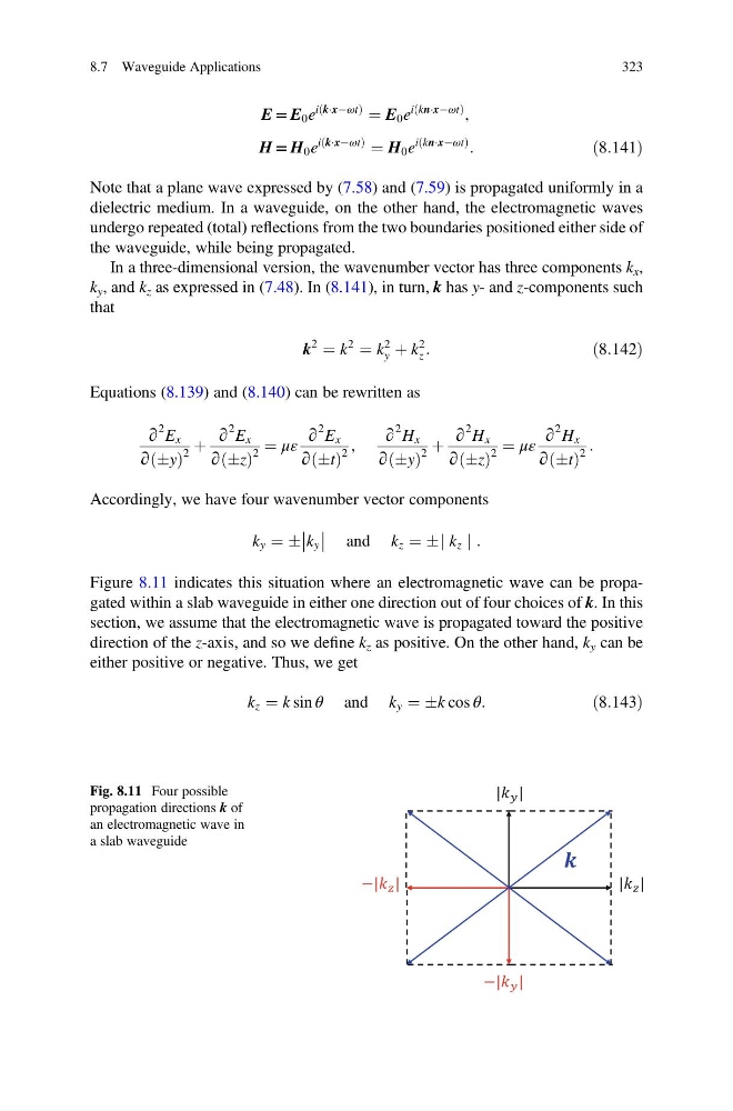
Accordingly, we have four wavenumber vector components
k y ¼ Æ k y
and k z ¼ Æj k z j :
Figure 8.11 indicates this situation where an electromagnetic wave can be propagated within a slab waveguide in either one direction out of four choices of k. In this
section, we assume that the electromagnetic wave is propagated toward the positive
direction of the z-axis, and so we define k z as positive. On the other hand, k y can be
either positive or negative. Thus, we get
k z ¼ k sin θ and k y ¼ Æk cos θ:
ð8:143Þ
| |
−| |
−| |
| |
Fig. 8.11 Four possible
propagation directions k of
an electromagnetic wave in
a slab waveguide
8.7 Waveguide Applications
323
i kÁxÀωt
ð
Þ
¼ E 0 e
i knÁxÀωt
ð
Þ ,
H = H 0 e
i kÁxÀωt
ð
Þ
¼ H 0 e
i knÁxÀωt
ð
Þ
:
ð8:141Þ
Note that a plane wave expressed by (7.58) and (7.59) is propagated uniformly in a
dielectric medium. In a waveguide, on the other hand, the electromagnetic waves
undergo repeated (total) reflections from the two boundaries positioned either side of
the waveguide, while being propagated.
In a three-dimensional version, the wavenumber vector has three components k x ,
k y , and k z as expressed in (7.48). In (8.141), in turn, k has y- and z-components such
that
k
2
¼ k
2
¼ k
2
y þ k
2
z :
ð8:142Þ
Equations (8.139) and (8.140) can be rewritten as
∂
2 E x
∂ Æy
ð Þ
2
þ
∂
2 E x
∂ Æz
ð Þ
2
¼ με
∂
2 E x
∂ Æt
ð Þ
2
,
∂
2 H x
∂ Æy
ð Þ
2
þ
∂
2 H x
∂ Æz
ð Þ
2
¼ με
∂
2 H x
∂ Æt
ð Þ
2
:
Accordingly, we have four wavenumber vector components
k y ¼ Æ k y
and k z ¼ Æj k z j :
Figure 8.11 indicates this situation where an electromagnetic wave can be propagated within a slab waveguide in either one direction out of four choices of k. In this
section, we assume that the electromagnetic wave is propagated toward the positive
direction of the z-axis, and so we define k z as positive. On the other hand, k y can be
either positive or negative. Thus, we get
k z ¼ k sin θ and k y ¼ Æk cos θ:
ð8:143Þ
| |
−| |
−| |
| |
Fig. 8.11 Four possible
propagation directions k of
an electromagnetic wave in
a slab waveguide
8.7 Waveguide Applications
323