

situation electromagnetic waves are confined within the slab. Moreover, only under a
restricted condition those waves are allowed to propagate in parallel to the slab
plane. Such electromagnetic waves are usually called propagation modes or simply
“modes.” An optical device thus designed is called a waveguide. These modes are
characterized by repeated total reflection during the propagation. Another mode is an
evanescent mode. Because of the total reflection, the energy transport is not allowed
to take place vertically to the interface of two dielectrics. For this reason, the
evanescent mode is thought to be propagated in parallel to the interface very close
to it.
8.7.1 TE and TM Waves in a Waveguide
In a waveguide configuration, propagating waves are classified into TE and TM
modes. Quality of materials that constitute a waveguide largely governs the propagation modes within the waveguide.
Figure 8.10 depicts a cross-section of a slab waveguide. We assume that the
electromagnetic wave is propagated toward the positive direction of the z-axis and
that a waveguide infinitely spreads toward the z- and x-axes. Suppose that the said
waveguide is spatially confined toward the y-axis. Let the thickness of the waveguide be d. From a point of view of material that shapes a waveguide, waveguides
are classified into two types. (i) Electromagnetic waves are completely confined
within the waveguide layer. This case typically happens when a dielectric forming
the waveguide is sandwiched between a couple of metal layers (Fig. 8.10a). This is
because the electromagnetic wave is not allowed to exist or propagate inside the
metal.
(ii) Electromagnetic waves are not completely confined within the waveguide.
This case happens when the dielectric of the waveguide is sandwiched by a couple of
1
i
β
=
= cos
1 −
1 +
= 2
0
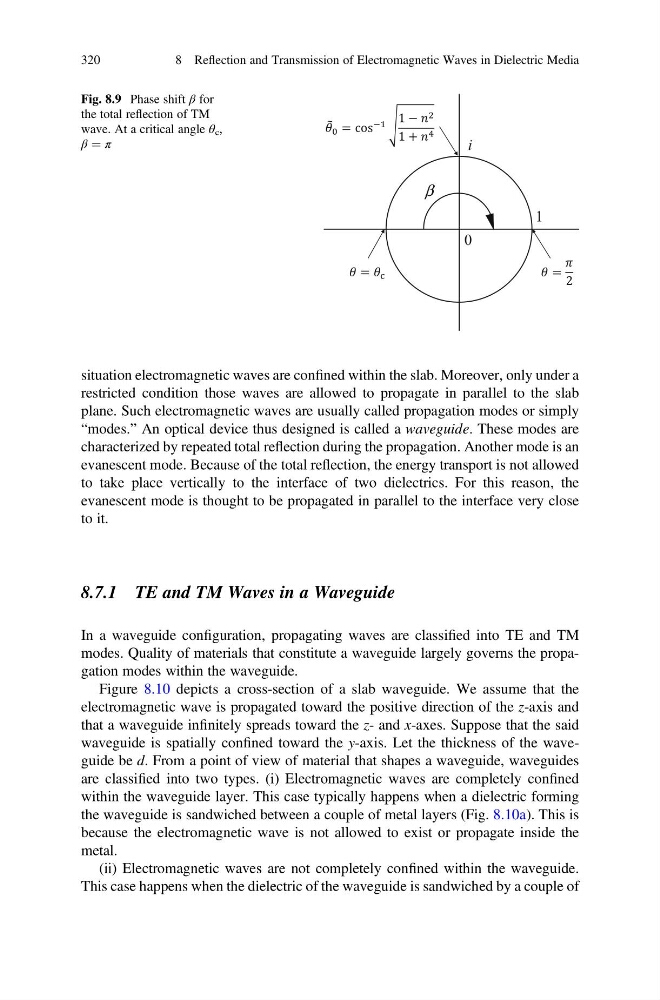
Fig. 8.9 Phase shift β for
the total reflection of TM
wave. At a critical angle θ c ,
β ¼ π
320
8 Reflection and Transmission of Electromagnetic Waves in Dielectric Media
restricted condition those waves are allowed to propagate in parallel to the slab
plane. Such electromagnetic waves are usually called propagation modes or simply
“modes.” An optical device thus designed is called a waveguide. These modes are
characterized by repeated total reflection during the propagation. Another mode is an
evanescent mode. Because of the total reflection, the energy transport is not allowed
to take place vertically to the interface of two dielectrics. For this reason, the
evanescent mode is thought to be propagated in parallel to the interface very close
to it.
8.7.1 TE and TM Waves in a Waveguide
In a waveguide configuration, propagating waves are classified into TE and TM
modes. Quality of materials that constitute a waveguide largely governs the propagation modes within the waveguide.
Figure 8.10 depicts a cross-section of a slab waveguide. We assume that the
electromagnetic wave is propagated toward the positive direction of the z-axis and
that a waveguide infinitely spreads toward the z- and x-axes. Suppose that the said
waveguide is spatially confined toward the y-axis. Let the thickness of the waveguide be d. From a point of view of material that shapes a waveguide, waveguides
are classified into two types. (i) Electromagnetic waves are completely confined
within the waveguide layer. This case typically happens when a dielectric forming
the waveguide is sandwiched between a couple of metal layers (Fig. 8.10a). This is
because the electromagnetic wave is not allowed to exist or propagate inside the
metal.
(ii) Electromagnetic waves are not completely confined within the waveguide.
This case happens when the dielectric of the waveguide is sandwiched by a couple of
1
i
β
=
= cos
1 −
1 +
= 2
0
Fig. 8.9 Phase shift β for
the total reflection of TM
wave. At a critical angle θ c ,
β ¼ π
320
8 Reflection and Transmission of Electromagnetic Waves in Dielectric Media