

7.3 A Short Description of a Conventional Gas-Phase Electron …
171
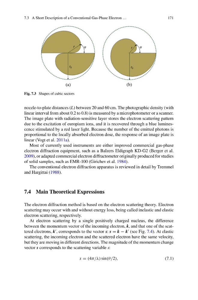
Fig. 7.3 Shapes of cubic sectors
nozzle-to-plate distances (L) between 20 and 60 cm. The photographic density (with
linear interval from about 0.2 to 0.8) is measured by a microphotometer or a scanner.
The image plate with radiation-sensitive layer stores the electron scattering pattern
due to the excitation of europium ions, and it is recovered through a blue luminescence stimulated by a red laser light. Because the number of the emitted photons is
proportional to the locally absorbed electron dose, the response of an image plate is
linear (Vogt et al. 2011a).
Most of currently used instruments are either improved commercial gas-phase
electron diffraction equipment, such as a Balzers Eldigraph KD-G2 (Berger et al.
2009), or adapted commercial electron diffractometer originally produced for studies
of solid samples, such as EMR-100 (Girichev et al. 1984).
The conventional electron diffraction apparatus is reviewed in detail by Tremmel
and Hargittai (1988).
7.4 Main Theoretical Expressions
The electron diffraction method is based on the electron scattering theory. Electron
scattering may occur with and without energy loss, being called inelastic and elastic
electron scattering, respectively.
At electron scattering by a single positively charged nucleus, the difference
between the momentum vector of the incoming electron, k, and that one of the scattered electrons, k
, corresponds to the vector s: s = k − k
(see Fig. 7.4). At elastic
scattering, the incoming electron and the scattered electron have the same velocity,
but they are moving in different directions. The magnitude of the momentum change
vector s corresponds to the scattering variable s:
s = (4π/λ) sin(θ/2),
(7.1)
171
Fig. 7.3 Shapes of cubic sectors
nozzle-to-plate distances (L) between 20 and 60 cm. The photographic density (with
linear interval from about 0.2 to 0.8) is measured by a microphotometer or a scanner.
The image plate with radiation-sensitive layer stores the electron scattering pattern
due to the excitation of europium ions, and it is recovered through a blue luminescence stimulated by a red laser light. Because the number of the emitted photons is
proportional to the locally absorbed electron dose, the response of an image plate is
linear (Vogt et al. 2011a).
Most of currently used instruments are either improved commercial gas-phase
electron diffraction equipment, such as a Balzers Eldigraph KD-G2 (Berger et al.
2009), or adapted commercial electron diffractometer originally produced for studies
of solid samples, such as EMR-100 (Girichev et al. 1984).
The conventional electron diffraction apparatus is reviewed in detail by Tremmel
and Hargittai (1988).
7.4 Main Theoretical Expressions
The electron diffraction method is based on the electron scattering theory. Electron
scattering may occur with and without energy loss, being called inelastic and elastic
electron scattering, respectively.
At electron scattering by a single positively charged nucleus, the difference
between the momentum vector of the incoming electron, k, and that one of the scattered electrons, k
, corresponds to the vector s: s = k − k
(see Fig. 7.4). At elastic
scattering, the incoming electron and the scattered electron have the same velocity,
but they are moving in different directions. The magnitude of the momentum change
vector s corresponds to the scattering variable s:
s = (4π/λ) sin(θ/2),
(7.1)