

250
S. Meyer et al.
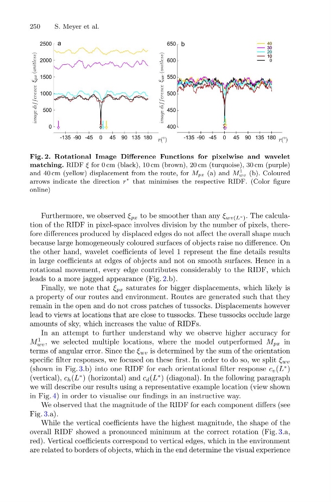
Fig. 2. Rotational Image Difference Functions for pixelwise and wavelet
matching. RIDF ξ for 0 cm (black), 10 cm (brown), 20 cm (turquoise), 30 cm (purple)
and 40 cm (yellow) displacement from the route, for Mpx (a) and M
1
wv (b). Coloured
arrows indicate the direction r
∗ that minimises the respective RIDF. (Color figure
online)
Furthermore, we observed ξ px to be smoother than any ξ wv(L ∗ ) . The calculation of the RIDF in pixel-space involves division by the number of pixels, therefore differences produced by displaced edges do not affect the overall shape much
because large homogeneously coloured surfaces of objects raise no difference. On
the other hand, wavelet coefficients of level 1 represent the fine details results
in large coefficients at edges of objects and not on smooth surfaces. Hence in a
rotational movement, every edge contributes considerably to the RIDF, which
leads to a more jagged appearance (Fig. 2.b).
Finally, we note that ξ px saturates for bigger displacements, which likely is
a property of our routes and environment. Routes are generated such that they
remain in the open and do not cross patches of tussocks. Displacements however
lead to views at locations that are close to tussocks. These tussocks occlude large
amounts of sky, which increases the value of RIDFs.
In an attempt to further understand why we observe higher accuracy for
M
1
wv , we selected multiple locations, where the model outperformed M px in
terms of angular error. Since the ξ wv is determined by the sum of the orientation
specific filter responses, we focused on these first. In order to do so, we split ξ wv
(shown in Fig. 3.b) into one RIDF for each orientational filter response c v (L
∗ )
(vertical), c h (L
∗ ) (horizontal) and c d (L
∗ ) (diagonal). In the following paragraph
we will describe our results using a representative example location (view shown
in Fig. 4) in order to visualise our findings in an instructive way.
We observed that the magnitude of the RIDF for each component differs (see
Fig. 3.a).
While the vertical coefficients have the highest magnitude, the shape of the
overall RIDF showed a pronounced minimum at the correct rotation (Fig. 3.a,
red). Vertical coefficients correspond to vertical edges, which in the environment
are related to borders of objects, which in the end determine the visual experience
S. Meyer et al.
Fig. 2. Rotational Image Difference Functions for pixelwise and wavelet
matching. RIDF ξ for 0 cm (black), 10 cm (brown), 20 cm (turquoise), 30 cm (purple)
and 40 cm (yellow) displacement from the route, for Mpx (a) and M
1
wv (b). Coloured
arrows indicate the direction r
∗ that minimises the respective RIDF. (Color figure
online)
Furthermore, we observed ξ px to be smoother than any ξ wv(L ∗ ) . The calculation of the RIDF in pixel-space involves division by the number of pixels, therefore differences produced by displaced edges do not affect the overall shape much
because large homogeneously coloured surfaces of objects raise no difference. On
the other hand, wavelet coefficients of level 1 represent the fine details results
in large coefficients at edges of objects and not on smooth surfaces. Hence in a
rotational movement, every edge contributes considerably to the RIDF, which
leads to a more jagged appearance (Fig. 2.b).
Finally, we note that ξ px saturates for bigger displacements, which likely is
a property of our routes and environment. Routes are generated such that they
remain in the open and do not cross patches of tussocks. Displacements however
lead to views at locations that are close to tussocks. These tussocks occlude large
amounts of sky, which increases the value of RIDFs.
In an attempt to further understand why we observe higher accuracy for
M
1
wv , we selected multiple locations, where the model outperformed M px in
terms of angular error. Since the ξ wv is determined by the sum of the orientation
specific filter responses, we focused on these first. In order to do so, we split ξ wv
(shown in Fig. 3.b) into one RIDF for each orientational filter response c v (L
∗ )
(vertical), c h (L
∗ ) (horizontal) and c d (L
∗ ) (diagonal). In the following paragraph
we will describe our results using a representative example location (view shown
in Fig. 4) in order to visualise our findings in an instructive way.
We observed that the magnitude of the RIDF for each component differs (see
Fig. 3.a).
While the vertical coefficients have the highest magnitude, the shape of the
overall RIDF showed a pronounced minimum at the correct rotation (Fig. 3.a,
red). Vertical coefficients correspond to vertical edges, which in the environment
are related to borders of objects, which in the end determine the visual experience