

Snapshot Navigation in the Wavelet Domain
249
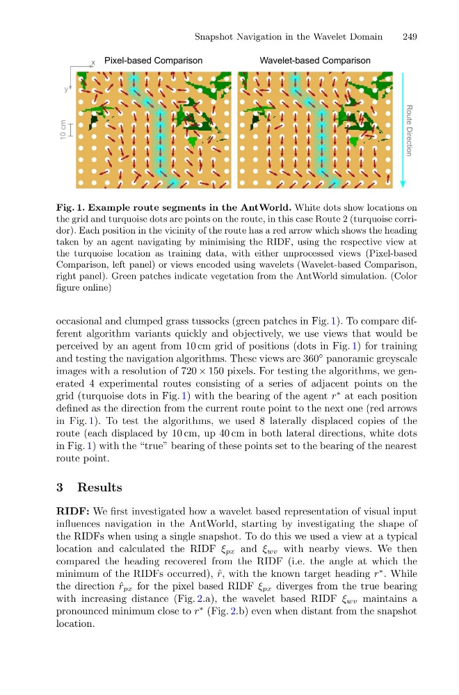
Fig. 1. Example route segments in the AntWorld. White dots show locations on
the grid and turquoise dots are points on the route, in this case Route 2 (turquoise corridor). Each position in the vicinity of the route has a red arrow which shows the heading
taken by an agent navigating by minimising the RIDF, using the respective view at
the turquoise location as training data, with either unprocessed views (Pixel-based
Comparison, left panel) or views encoded using wavelets (Wavelet-based Comparison,
right panel). Green patches indicate vegetation from the AntWorld simulation. (Color
figure online)
occasional and clumped grass tussocks (green patches in Fig. 1). To compare different algorithm variants quickly and objectively, we use views that would be
perceived by an agent from 10 cm grid of positions (dots in Fig. 1) for training
and testing the navigation algorithms. These views are 360
◦ panoramic greyscale
images with a resolution of 720 × 150 pixels. For testing the algorithms, we generated 4 experimental routes consisting of a series of adjacent points on the
grid (turquoise dots in Fig. 1) with the bearing of the agent r
∗ at each position
defined as the direction from the current route point to the next one (red arrows
in Fig. 1). To test the algorithms, we used 8 laterally displaced copies of the
route (each displaced by 10 cm, up 40 cm in both lateral directions, white dots
in Fig. 1) with the “true” bearing of these points set to the bearing of the nearest
route point.
3 Results
RIDF: We first investigated how a wavelet based representation of visual input
influences navigation in the AntWorld, starting by investigating the shape of
the RIDFs when using a single snapshot. To do this we used a view at a typical
location and calculated the RIDF ξ px and ξ wv with nearby views. We then
compared the heading recovered from the RIDF (i.e. the angle at which the
minimum of the RIDFs occurred), ˆ
r, with the known target heading r
∗ . While
the direction ˆ
r px for the pixel based RIDF ξ px diverges from the true bearing
with increasing distance (Fig. 2.a), the wavelet based RIDF ξ wv maintains a
pronounced minimum close to r
∗ (Fig. 2.b) even when distant from the snapshot
location.
249
Fig. 1. Example route segments in the AntWorld. White dots show locations on
the grid and turquoise dots are points on the route, in this case Route 2 (turquoise corridor). Each position in the vicinity of the route has a red arrow which shows the heading
taken by an agent navigating by minimising the RIDF, using the respective view at
the turquoise location as training data, with either unprocessed views (Pixel-based
Comparison, left panel) or views encoded using wavelets (Wavelet-based Comparison,
right panel). Green patches indicate vegetation from the AntWorld simulation. (Color
figure online)
occasional and clumped grass tussocks (green patches in Fig. 1). To compare different algorithm variants quickly and objectively, we use views that would be
perceived by an agent from 10 cm grid of positions (dots in Fig. 1) for training
and testing the navigation algorithms. These views are 360
◦ panoramic greyscale
images with a resolution of 720 × 150 pixels. For testing the algorithms, we generated 4 experimental routes consisting of a series of adjacent points on the
grid (turquoise dots in Fig. 1) with the bearing of the agent r
∗ at each position
defined as the direction from the current route point to the next one (red arrows
in Fig. 1). To test the algorithms, we used 8 laterally displaced copies of the
route (each displaced by 10 cm, up 40 cm in both lateral directions, white dots
in Fig. 1) with the “true” bearing of these points set to the bearing of the nearest
route point.
3 Results
RIDF: We first investigated how a wavelet based representation of visual input
influences navigation in the AntWorld, starting by investigating the shape of
the RIDFs when using a single snapshot. To do this we used a view at a typical
location and calculated the RIDF ξ px and ξ wv with nearby views. We then
compared the heading recovered from the RIDF (i.e. the angle at which the
minimum of the RIDFs occurred), ˆ
r, with the known target heading r
∗ . While
the direction ˆ
r px for the pixel based RIDF ξ px diverges from the true bearing
with increasing distance (Fig. 2.a), the wavelet based RIDF ξ wv maintains a
pronounced minimum close to r
∗ (Fig. 2.b) even when distant from the snapshot
location.