

184
S. Iacob et al.
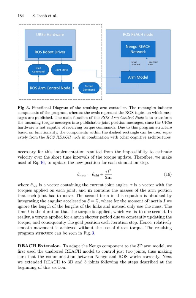
Fig. 3. Functional Diagram of the resulting arm controller. The rectangles indicate
components of the program, whereas the ovals represent the ROS topics on which messages are published. The main function of the ROS Arm Control Node is to transform
the incoming torque messages into publishable joint position messages, since the UR5e
hardware is not capable of receiving torque commands. Due to this program structure
based on functionality, the components within the dashed rectangle can be used separately from the ROS REACH node in combination with other cognitive architectures
necessary for this implementation resulted from the impossibility to estimate
velocity over the short time intervals of the torque update. Therefore, we make
used of Eq. 16, to update the new position for each simulation step.
θ new = θ old +
τ t
2
2m
(16)
where θ old is a vector containing the current joint angles, τ is a vector with the
torques applied on each joint, and m contains the masses of the arm portion
that each joint has to move. The second term in this equation is obtained by
integrating the angular acceleration ¨
q =
τ
I , where for the moment of inertia I we
ignore the length of the lengths of the links and instead only use the mass. The
time t is the duration that the torque is applied, which we fix to one second. In
reality, a torque applied for a much shorter period due to constantly updating the
torque, and consequently the goal position each iteration step. Hence, relatively
smooth movement is achieved without the use of direct torque. The resulting
program structure can be seen in Fig. 3.
REACH Extension. To adapt the Nengo component to the 3D arm model, we
first used the unaltered REACH model to control just two joints, thus making
sure that the communication between Nengo and ROS works correctly. Next
we extended REACH to 3D and 3 joints following the steps described at the
beginning of this section.
S. Iacob et al.
Fig. 3. Functional Diagram of the resulting arm controller. The rectangles indicate
components of the program, whereas the ovals represent the ROS topics on which messages are published. The main function of the ROS Arm Control Node is to transform
the incoming torque messages into publishable joint position messages, since the UR5e
hardware is not capable of receiving torque commands. Due to this program structure
based on functionality, the components within the dashed rectangle can be used separately from the ROS REACH node in combination with other cognitive architectures
necessary for this implementation resulted from the impossibility to estimate
velocity over the short time intervals of the torque update. Therefore, we make
used of Eq. 16, to update the new position for each simulation step.
θ new = θ old +
τ t
2
2m
(16)
where θ old is a vector containing the current joint angles, τ is a vector with the
torques applied on each joint, and m contains the masses of the arm portion
that each joint has to move. The second term in this equation is obtained by
integrating the angular acceleration ¨
q =
τ
I , where for the moment of inertia I we
ignore the length of the lengths of the links and instead only use the mass. The
time t is the duration that the torque is applied, which we fix to one second. In
reality, a torque applied for a much shorter period due to constantly updating the
torque, and consequently the goal position each iteration step. Hence, relatively
smooth movement is achieved without the use of direct torque. The resulting
program structure can be seen in Fig. 3.
REACH Extension. To adapt the Nengo component to the 3D arm model, we
first used the unaltered REACH model to control just two joints, thus making
sure that the communication between Nengo and ROS works correctly. Next
we extended REACH to 3D and 3 joints following the steps described at the
beginning of this section.