

From Models of Cognition to Robot Control and Back Using SNNs
183
Inertia Matrix. Secondly we go through the process of creating the inertia
matrix in hand-space (i.e. cartesian space) M x , which is used for compensation
of the movement-generated inertia. This compensation is achieved by multiplying
the Jacobian with the inertia matrix M x .
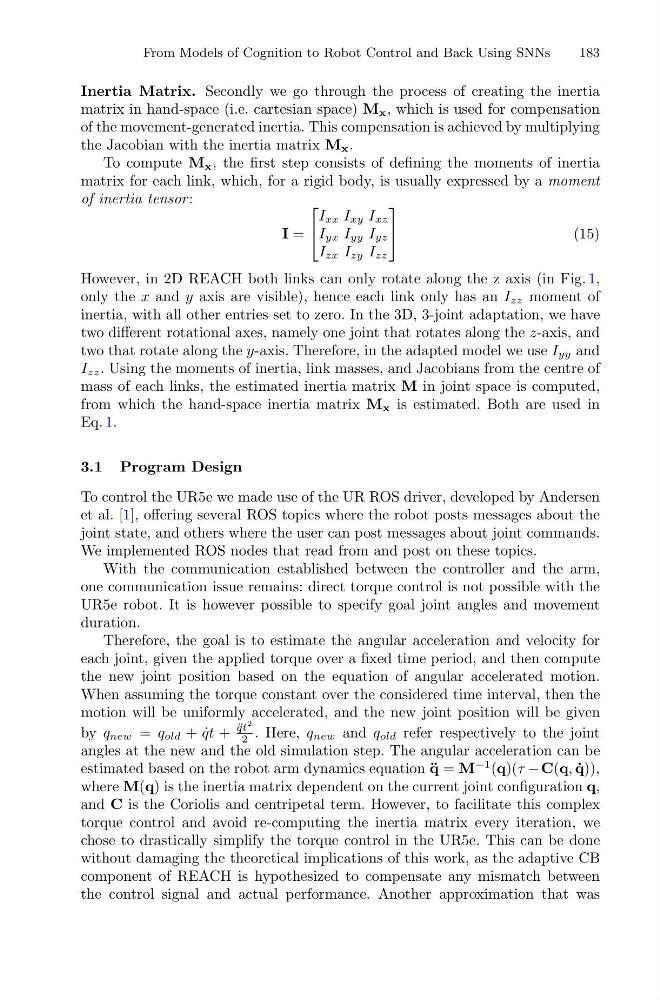
To compute M x , the first step consists of defining the moments of inertia
matrix for each link, which, for a rigid body, is usually expressed by a moment
of inertia tensor :
I =
⎡
⎣
I xx I xy I xz
I yx I yy I yz
I zx I zy I zz
⎤
⎦
(15)
However, in 2D REACH both links can only rotate along the z axis (in Fig. 1,
only the x and y axis are visible), hence each link only has an I zz moment of
inertia, with all other entries set to zero. In the 3D, 3-joint adaptation, we have
two different rotational axes, namely one joint that rotates along the z-axis, and
two that rotate along the y-axis. Therefore, in the adapted model we use I yy and
I zz . Using the moments of inertia, link masses, and Jacobians from the centre of
mass of each links, the estimated inertia matrix M in joint space is computed,
from which the hand-space inertia matrix M x is estimated. Both are used in
Eq. 1.
3.1 Program Design
To control the UR5e we made use of the UR ROS driver, developed by Andersen
et al. [1], offering several ROS topics where the robot posts messages about the
joint state, and others where the user can post messages about joint commands.
We implemented ROS nodes that read from and post on these topics.
With the communication established between the controller and the arm,
one communication issue remains: direct torque control is not possible with the
UR5e robot. It is however possible to specify goal joint angles and movement
duration.
Therefore, the goal is to estimate the angular acceleration and velocity for
each joint, given the applied torque over a fixed time period, and then compute
the new joint position based on the equation of angular accelerated motion.
When assuming the torque constant over the considered time interval, then the
motion will be uniformly accelerated, and the new joint position will be given
by q new = q old + ˙
qt +
¨
qt
2
2 . Here, q new and q old refer respectively to the joint
angles at the new and the old simulation step. The angular acceleration can be
estimated based on the robot arm dynamics equation ¨
q = M
−1 (q)(τ − C(q, ˙
q)),
where M(q) is the inertia matrix dependent on the current joint configuration q,
and C is the Coriolis and centripetal term. However, to facilitate this complex
torque control and avoid re-computing the inertia matrix every iteration, we
chose to drastically simplify the torque control in the UR5e. This can be done
without damaging the theoretical implications of this work, as the adaptive CB
component of REACH is hypothesized to compensate any mismatch between
the control signal and actual performance. Another approximation that was
183
Inertia Matrix. Secondly we go through the process of creating the inertia
matrix in hand-space (i.e. cartesian space) M x , which is used for compensation
of the movement-generated inertia. This compensation is achieved by multiplying
the Jacobian with the inertia matrix M x .
To compute M x , the first step consists of defining the moments of inertia
matrix for each link, which, for a rigid body, is usually expressed by a moment
of inertia tensor :
I =
⎡
⎣
I xx I xy I xz
I yx I yy I yz
I zx I zy I zz
⎤
⎦
(15)
However, in 2D REACH both links can only rotate along the z axis (in Fig. 1,
only the x and y axis are visible), hence each link only has an I zz moment of
inertia, with all other entries set to zero. In the 3D, 3-joint adaptation, we have
two different rotational axes, namely one joint that rotates along the z-axis, and
two that rotate along the y-axis. Therefore, in the adapted model we use I yy and
I zz . Using the moments of inertia, link masses, and Jacobians from the centre of
mass of each links, the estimated inertia matrix M in joint space is computed,
from which the hand-space inertia matrix M x is estimated. Both are used in
Eq. 1.
3.1 Program Design
To control the UR5e we made use of the UR ROS driver, developed by Andersen
et al. [1], offering several ROS topics where the robot posts messages about the
joint state, and others where the user can post messages about joint commands.
We implemented ROS nodes that read from and post on these topics.
With the communication established between the controller and the arm,
one communication issue remains: direct torque control is not possible with the
UR5e robot. It is however possible to specify goal joint angles and movement
duration.
Therefore, the goal is to estimate the angular acceleration and velocity for
each joint, given the applied torque over a fixed time period, and then compute
the new joint position based on the equation of angular accelerated motion.
When assuming the torque constant over the considered time interval, then the
motion will be uniformly accelerated, and the new joint position will be given
by q new = q old + ˙
qt +
¨
qt
2
2 . Here, q new and q old refer respectively to the joint
angles at the new and the old simulation step. The angular acceleration can be
estimated based on the robot arm dynamics equation ¨
q = M
−1 (q)(τ − C(q, ˙
q)),
where M(q) is the inertia matrix dependent on the current joint configuration q,
and C is the Coriolis and centripetal term. However, to facilitate this complex
torque control and avoid re-computing the inertia matrix every iteration, we
chose to drastically simplify the torque control in the UR5e. This can be done
without damaging the theoretical implications of this work, as the adaptive CB
component of REACH is hypothesized to compensate any mismatch between
the control signal and actual performance. Another approximation that was