

432
A. V. Maslov and V. N. Astratov
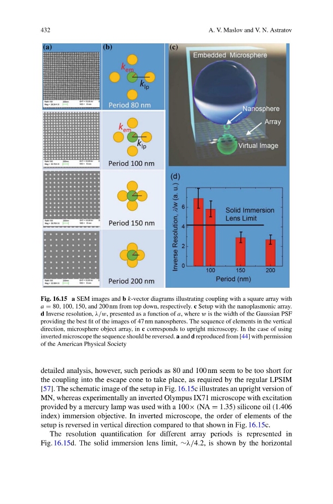
Fig. 16.15 a SEM images and b k-vector diagrams illustrating coupling with a square array with
a = 80, 100, 150, and 200 nm from top down, respectively. c Setup with the nanoplasmonic array.
d Inverse resolution, λ/w, presented as a function of a, where w is the width of the Gaussian PSF
providing the best fit of the images of 47 nm nanospheres. The sequence of elements in the vertical
direction, microsphere object array, in c corresponds to upright microscopy. In the case of using
inverted microscope the sequence should be reversed. a and d reproduced from [44] with permission
of the American Physical Society
detailed analysis, however, such periods as 80 and 100 nm seem to be too short for
the coupling into the escape cone to take place, as required by the regular LPSIM
[57]. The schematic image of the setup in Fig. 16.15c illustrates an upright version of
MN, whereas experimentally an inverted Olympus IX71 microscope with excitation
provided by a mercury lamp was used with a 100× (NA = 1.35) silicone oil (1.406
index) immersion objective. In inverted microscope, the order of elements of the
setup is reversed in vertical direction compared to that shown in Fig. 16.15c.
The resolution quantification for different array periods is represented in
Fig. 16.15d. The solid immersion lens limit, ∼λ/4.2, is shown by the horizontal
A. V. Maslov and V. N. Astratov
Fig. 16.15 a SEM images and b k-vector diagrams illustrating coupling with a square array with
a = 80, 100, 150, and 200 nm from top down, respectively. c Setup with the nanoplasmonic array.
d Inverse resolution, λ/w, presented as a function of a, where w is the width of the Gaussian PSF
providing the best fit of the images of 47 nm nanospheres. The sequence of elements in the vertical
direction, microsphere object array, in c corresponds to upright microscopy. In the case of using
inverted microscope the sequence should be reversed. a and d reproduced from [44] with permission
of the American Physical Society
detailed analysis, however, such periods as 80 and 100 nm seem to be too short for
the coupling into the escape cone to take place, as required by the regular LPSIM
[57]. The schematic image of the setup in Fig. 16.15c illustrates an upright version of
MN, whereas experimentally an inverted Olympus IX71 microscope with excitation
provided by a mercury lamp was used with a 100× (NA = 1.35) silicone oil (1.406
index) immersion objective. In inverted microscope, the order of elements of the
setup is reversed in vertical direction compared to that shown in Fig. 16.15c.
The resolution quantification for different array periods is represented in
Fig. 16.15d. The solid immersion lens limit, ∼λ/4.2, is shown by the horizontal