

390
Z. Wang and B. Luk’yanchuk
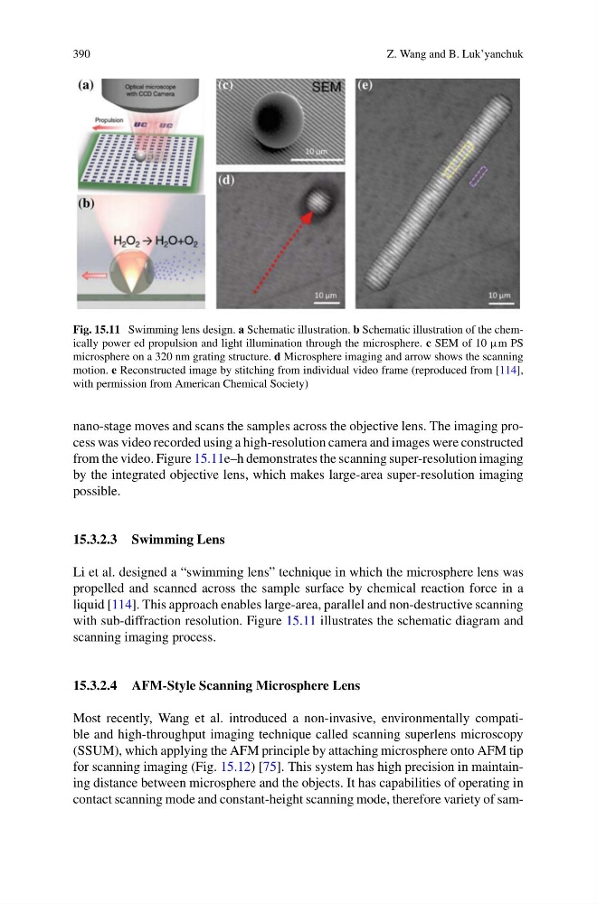
Fig. 15.11 Swimming lens design. a Schematic illustration. b Schematic illustration of the chemically power ed propulsion and light illumination through the microsphere. c SEM of 10 μm PS
microsphere on a 320 nm grating structure. d Microsphere imaging and arrow shows the scanning
motion. e Reconstructed image by stitching from individual video frame (reproduced from [114],
with permission from American Chemical Society)
nano-stage moves and scans the samples across the objective lens. The imaging process was video recorded using a high-resolution camera and images were constructed
from the video. Figure 15.11e–h demonstrates the scanning super-resolution imaging
by the integrated objective lens, which makes large-area super-resolution imaging
possible.
15.3.2.3 Swimming Lens
Li et al. designed a “swimming lens” technique in which the microsphere lens was
propelled and scanned across the sample surface by chemical reaction force in a
liquid [114]. This approach enables large-area, parallel and non-destructive scanning
with sub-diffraction resolution. Figure 15.11 illustrates the schematic diagram and
scanning imaging process.
15.3.2.4 AFM-Style Scanning Microsphere Lens
Most recently, Wang et al. introduced a non-invasive, environmentally compatible and high-throughput imaging technique called scanning superlens microscopy
(SSUM), which applying the AFM principle by attaching microsphere onto AFM tip
for scanning imaging (Fig. 15.12) [75]. This system has high precision in maintaining distance between microsphere and the objects. It has capabilities of operating in
contact scanning mode and constant-height scanning mode, therefore variety of sam-
Z. Wang and B. Luk’yanchuk
Fig. 15.11 Swimming lens design. a Schematic illustration. b Schematic illustration of the chemically power ed propulsion and light illumination through the microsphere. c SEM of 10 μm PS
microsphere on a 320 nm grating structure. d Microsphere imaging and arrow shows the scanning
motion. e Reconstructed image by stitching from individual video frame (reproduced from [114],
with permission from American Chemical Society)
nano-stage moves and scans the samples across the objective lens. The imaging process was video recorded using a high-resolution camera and images were constructed
from the video. Figure 15.11e–h demonstrates the scanning super-resolution imaging
by the integrated objective lens, which makes large-area super-resolution imaging
possible.
15.3.2.3 Swimming Lens
Li et al. designed a “swimming lens” technique in which the microsphere lens was
propelled and scanned across the sample surface by chemical reaction force in a
liquid [114]. This approach enables large-area, parallel and non-destructive scanning
with sub-diffraction resolution. Figure 15.11 illustrates the schematic diagram and
scanning imaging process.
15.3.2.4 AFM-Style Scanning Microsphere Lens
Most recently, Wang et al. introduced a non-invasive, environmentally compatible and high-throughput imaging technique called scanning superlens microscopy
(SSUM), which applying the AFM principle by attaching microsphere onto AFM tip
for scanning imaging (Fig. 15.12) [75]. This system has high precision in maintaining distance between microsphere and the objects. It has capabilities of operating in
contact scanning mode and constant-height scanning mode, therefore variety of sam-