

15 Super-Resolution Imaging and Microscopy by Dielectric …
389
design which solves the synchronisation problem of coverslip superlens and objective lens. The idea is to use a custom-made lens adaptor to integrate these two lenses
to form a superlensing microscope objective lens.
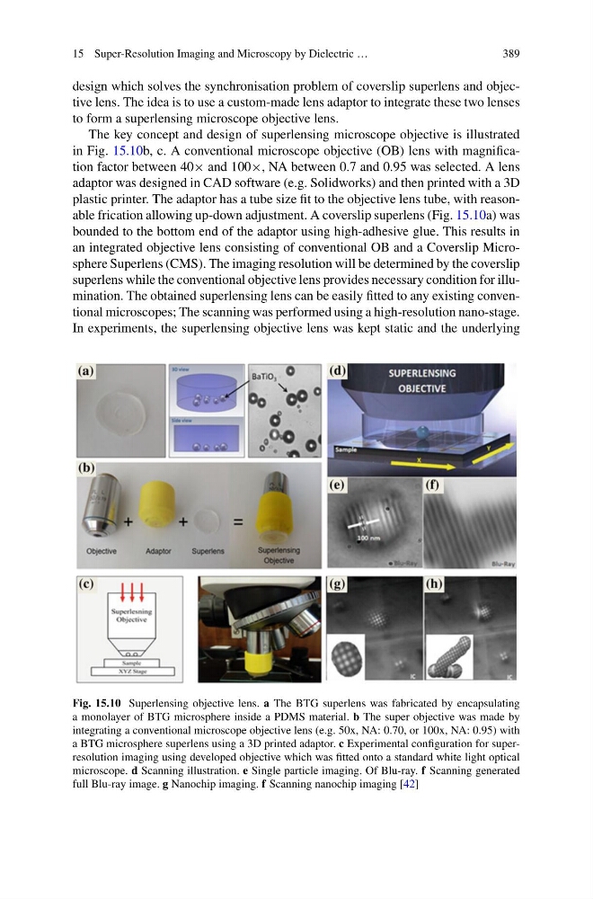
The key concept and design of superlensing microscope objective is illustrated
in Fig. 15.10b, c. A conventional microscope objective (OB) lens with magnification factor between 40× and 100×, NA between 0.7 and 0.95 was selected. A lens
adaptor was designed in CAD software (e.g. Solidworks) and then printed with a 3D
plastic printer. The adaptor has a tube size fit to the objective lens tube, with reasonable frication allowing up-down adjustment. A coverslip superlens (Fig. 15.10a) was
bounded to the bottom end of the adaptor using high-adhesive glue. This results in
an integrated objective lens consisting of conventional OB and a Coverslip Microsphere Superlens (CMS). The imaging resolution will be determined by the coverslip
superlens while the conventional objective lens provides necessary condition for illumination. The obtained superlensing lens can be easily fitted to any existing conventional microscopes; The scanning was performed using a high-resolution nano-stage.
In experiments, the superlensing objective lens was kept static and the underlying
Fig. 15.10 Superlensing objective lens. a The BTG superlens was fabricated by encapsulating
a monolayer of BTG microsphere inside a PDMS material. b The super objective was made by
integrating a conventional microscope objective lens (e.g. 50x, NA: 0.70, or 100x, NA: 0.95) with
a BTG microsphere superlens using a 3D printed adaptor. c Experimental configuration for superresolution imaging using developed objective which was fitted onto a standard white light optical
microscope. d Scanning illustration. e Single particle imaging. Of Blu-ray. f Scanning generated
full Blu-ray image. g Nanochip imaging. f Scanning nanochip imaging [42]
389
design which solves the synchronisation problem of coverslip superlens and objective lens. The idea is to use a custom-made lens adaptor to integrate these two lenses
to form a superlensing microscope objective lens.
The key concept and design of superlensing microscope objective is illustrated
in Fig. 15.10b, c. A conventional microscope objective (OB) lens with magnification factor between 40× and 100×, NA between 0.7 and 0.95 was selected. A lens
adaptor was designed in CAD software (e.g. Solidworks) and then printed with a 3D
plastic printer. The adaptor has a tube size fit to the objective lens tube, with reasonable frication allowing up-down adjustment. A coverslip superlens (Fig. 15.10a) was
bounded to the bottom end of the adaptor using high-adhesive glue. This results in
an integrated objective lens consisting of conventional OB and a Coverslip Microsphere Superlens (CMS). The imaging resolution will be determined by the coverslip
superlens while the conventional objective lens provides necessary condition for illumination. The obtained superlensing lens can be easily fitted to any existing conventional microscopes; The scanning was performed using a high-resolution nano-stage.
In experiments, the superlensing objective lens was kept static and the underlying
Fig. 15.10 Superlensing objective lens. a The BTG superlens was fabricated by encapsulating
a monolayer of BTG microsphere inside a PDMS material. b The super objective was made by
integrating a conventional microscope objective lens (e.g. 50x, NA: 0.70, or 100x, NA: 0.95) with
a BTG microsphere superlens using a 3D printed adaptor. c Experimental configuration for superresolution imaging using developed objective which was fitted onto a standard white light optical
microscope. d Scanning illustration. e Single particle imaging. Of Blu-ray. f Scanning generated
full Blu-ray image. g Nanochip imaging. f Scanning nanochip imaging [42]