

14 Label-Free Super-Resolution Imaging with Hyperbolic Materials
361
with the increase of the separation between the object and the top surface, eventually
approaching the diffraction-limited value of a quarter of a wavelength as in the
conventional structured illumination. This prevents the use of HSI as an optical
tomography technique.
Furthermore, imaging based on the hyperstructured illumination will show substantial aberrations in the case of the objects that are highly dispersive in the wavelength range of illumination.
14.6.2 HSI: Theoretical Description
Hyperstructured illumination imaging relies on the information carried out by the
light scattered from the object at various wavelengths. When both the amplitude and
the phase information can be measured of the far field, the resulting mathematical
problem is linear, well defined and allows a highly efficient numerical solution in real
time. In the present section, we describe the corresponding mathematical framework
for image reconstruction.
We note however that coherent detection is not necessary for accurate image
reconstruction. With a trade-off in efficiency, hyperstructured illumination imaging
can also be used in the case when only the amplitude (or intensity) of the far field is
available [57].
The object profile can be represented by its permittivity contrast (r). Since the
field outside the hyperbolic substrate is exponentially decaying away from the object
plane at the surface of the hyperbolic metamaterial, different parts of the object that is
located at different “height” z (see Fig. 14.11), are illuminated at different intensities.
As a result, the information sent to the far field is not of a full 3D hologram of the object
but its Motti projection [29]. While this projection contains contributions from all
portions of the object, their relative weights decrease with the corresponding height
z. Figure 14.12 shows an example of a target and its Motti projection.
When the object at the “top” surface of the hyperbolic substrate is illuminated by
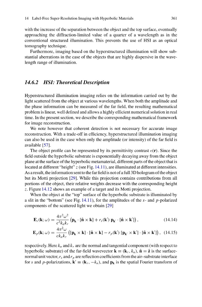
a slit in the “bottom” (see Fig. 14.11), for the amplitudes of the s- and p-polarized
components of the scattered light we obtain [29]
E s (k; ω) =
4π
2
ω
2
c 2 k n k τ
p k · [ˆ n × k] + r s (k
) p k
· [ˆ n × k
]
,
(14.14)
E p (k; ω) =
4π
2
ω
ck n k τ
[p k × k] · [ˆ n × k] − r p (k
) [p k
× k
] · [ˆ n × k
]
, (14.15)
respectively. Here k n and k τ are the normal and tangential component (with respect to
hyperbolic substrate) of the far-field wavevector k ≡ (k τ , k n ), ˆ
n = ˆ
z is the surfacenormal unit vector, r s and r p are reflection coefficients from the air–substrate interface
for s and p-polarizations, k
≡ (k τ , −k n ), and p k is the spatial Fourier transform of
361
with the increase of the separation between the object and the top surface, eventually
approaching the diffraction-limited value of a quarter of a wavelength as in the
conventional structured illumination. This prevents the use of HSI as an optical
tomography technique.
Furthermore, imaging based on the hyperstructured illumination will show substantial aberrations in the case of the objects that are highly dispersive in the wavelength range of illumination.
14.6.2 HSI: Theoretical Description
Hyperstructured illumination imaging relies on the information carried out by the
light scattered from the object at various wavelengths. When both the amplitude and
the phase information can be measured of the far field, the resulting mathematical
problem is linear, well defined and allows a highly efficient numerical solution in real
time. In the present section, we describe the corresponding mathematical framework
for image reconstruction.
We note however that coherent detection is not necessary for accurate image
reconstruction. With a trade-off in efficiency, hyperstructured illumination imaging
can also be used in the case when only the amplitude (or intensity) of the far field is
available [57].
The object profile can be represented by its permittivity contrast (r). Since the
field outside the hyperbolic substrate is exponentially decaying away from the object
plane at the surface of the hyperbolic metamaterial, different parts of the object that is
located at different “height” z (see Fig. 14.11), are illuminated at different intensities.
As a result, the information sent to the far field is not of a full 3D hologram of the object
but its Motti projection [29]. While this projection contains contributions from all
portions of the object, their relative weights decrease with the corresponding height
z. Figure 14.12 shows an example of a target and its Motti projection.
When the object at the “top” surface of the hyperbolic substrate is illuminated by
a slit in the “bottom” (see Fig. 14.11), for the amplitudes of the s- and p-polarized
components of the scattered light we obtain [29]
E s (k; ω) =
4π
2
ω
2
c 2 k n k τ
p k · [ˆ n × k] + r s (k
) p k
· [ˆ n × k
]
,
(14.14)
E p (k; ω) =
4π
2
ω
ck n k τ
[p k × k] · [ˆ n × k] − r p (k
) [p k
× k
] · [ˆ n × k
]
, (14.15)
respectively. Here k n and k τ are the normal and tangential component (with respect to
hyperbolic substrate) of the far-field wavevector k ≡ (k τ , k n ), ˆ
n = ˆ
z is the surfacenormal unit vector, r s and r p are reflection coefficients from the air–substrate interface
for s and p-polarizations, k
≡ (k τ , −k n ), and p k is the spatial Fourier transform of