

332
I. I. Smolyaninov and V. N. Smolyaninova
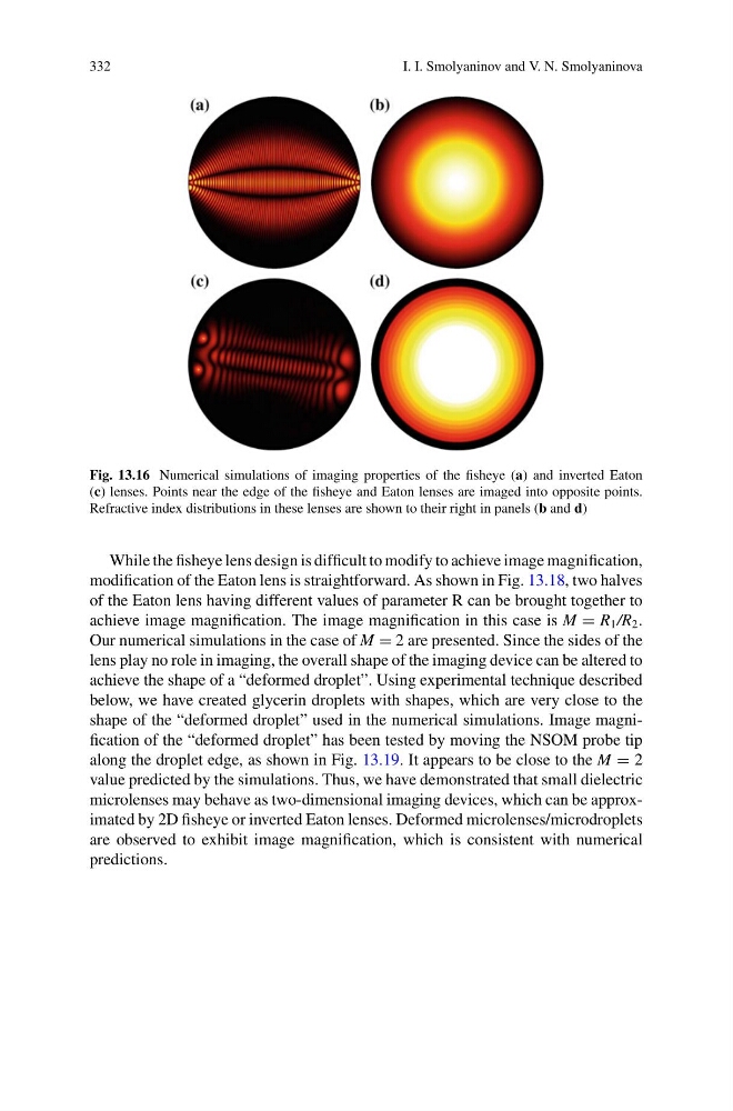
Fig. 13.16 Numerical simulations of imaging properties of the fisheye (a) and inverted Eaton
(c) lenses. Points near the edge of the fisheye and Eaton lenses are imaged into opposite points.
Refractive index distributions in these lenses are shown to their right in panels (b and d)
While the fisheye lens design is difficult to modify to achieve image magnification,
modification of the Eaton lens is straightforward. As shown in Fig. 13.18, two halves
of the Eaton lens having different values of parameter R can be brought together to
achieve image magnification. The image magnification in this case is M = R 1 /R 2 .
Our numerical simulations in the case of M = 2 are presented. Since the sides of the
lens play no role in imaging, the overall shape of the imaging device can be altered to
achieve the shape of a “deformed droplet”. Using experimental technique described
below, we have created glycerin droplets with shapes, which are very close to the
shape of the “deformed droplet” used in the numerical simulations. Image magnification of the “deformed droplet” has been tested by moving the NSOM probe tip
along the droplet edge, as shown in Fig. 13.19. It appears to be close to the M = 2
value predicted by the simulations. Thus, we have demonstrated that small dielectric
microlenses may behave as two-dimensional imaging devices, which can be approximated by 2D fisheye or inverted Eaton lenses. Deformed microlenses/microdroplets
are observed to exhibit image magnification, which is consistent with numerical
predictions.
I. I. Smolyaninov and V. N. Smolyaninova
Fig. 13.16 Numerical simulations of imaging properties of the fisheye (a) and inverted Eaton
(c) lenses. Points near the edge of the fisheye and Eaton lenses are imaged into opposite points.
Refractive index distributions in these lenses are shown to their right in panels (b and d)
While the fisheye lens design is difficult to modify to achieve image magnification,
modification of the Eaton lens is straightforward. As shown in Fig. 13.18, two halves
of the Eaton lens having different values of parameter R can be brought together to
achieve image magnification. The image magnification in this case is M = R 1 /R 2 .
Our numerical simulations in the case of M = 2 are presented. Since the sides of the
lens play no role in imaging, the overall shape of the imaging device can be altered to
achieve the shape of a “deformed droplet”. Using experimental technique described
below, we have created glycerin droplets with shapes, which are very close to the
shape of the “deformed droplet” used in the numerical simulations. Image magnification of the “deformed droplet” has been tested by moving the NSOM probe tip
along the droplet edge, as shown in Fig. 13.19. It appears to be close to the M = 2
value predicted by the simulations. Thus, we have demonstrated that small dielectric
microlenses may behave as two-dimensional imaging devices, which can be approximated by 2D fisheye or inverted Eaton lenses. Deformed microlenses/microdroplets
are observed to exhibit image magnification, which is consistent with numerical
predictions.