

13 Super-Resolution Microscopy Techniques Based …
323
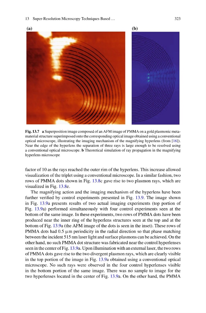
Fig. 13.7 a Superposition image composed of an AFM image of PMMA on a gold plasmonic metamaterial structure superimposed onto the corresponding optical image obtained using a conventional
optical microscope, illustrating the imaging mechanism of the magnifying hyperlens (from [16]).
Near the edge of the hyperlens the separation of three rays is large enough to be resolved using
a conventional optical microscope. b Theoretical simulation of ray propagation in the magnifying
hyperlens microscope
factor of 10 as the rays reached the outer rim of the hyperlens. This increase allowed
visualization of the triplet using a conventional microscope. In a similar fashion, two
rows of PMMA dots shown in Fig. 13.8c gave rise to two plasmon rays, which are
visualized in Fig. 13.8e.
The magnifying action and the imaging mechanism of the hyperlens have been
further verified by control experiments presented in Fig. 13.9. The image shown
in Fig. 13.9a presents results of two actual imaging experiments (top portion of
Fig. 13.9a) performed simultaneously with four control experiments seen at the
bottom of the same image. In these experiments, two rows of PMMA dots have been
produced near the inner ring of the hyperlens structures seen at the top and at the
bottom of Fig. 13.9a (the AFM image of the dots is seen in the inset). These rows of
PMMA dots had 0.5 µm periodicity in the radial direction so that phase matching
between the incident 515 nm laser light and surface plasmons can be achieved. On the
other hand, no such PMMA dot structure was fabricated near the control hyperlenses
seen in the center of Fig. 13.9a. Upon illumination with an external laser, the two rows
of PMMA dots gave rise to the two divergent plasmon rays, which are clearly visible
in the top portion of the image in Fig. 13.9a obtained using a conventional optical
microscope. No such rays were observed in the four control hyperlenses visible
in the bottom portion of the same image. There was no sample to image for the
two hyperlenses located in the center of Fig. 13.9a. On the other hand, the PMMA
323
Fig. 13.7 a Superposition image composed of an AFM image of PMMA on a gold plasmonic metamaterial structure superimposed onto the corresponding optical image obtained using a conventional
optical microscope, illustrating the imaging mechanism of the magnifying hyperlens (from [16]).
Near the edge of the hyperlens the separation of three rays is large enough to be resolved using
a conventional optical microscope. b Theoretical simulation of ray propagation in the magnifying
hyperlens microscope
factor of 10 as the rays reached the outer rim of the hyperlens. This increase allowed
visualization of the triplet using a conventional microscope. In a similar fashion, two
rows of PMMA dots shown in Fig. 13.8c gave rise to two plasmon rays, which are
visualized in Fig. 13.8e.
The magnifying action and the imaging mechanism of the hyperlens have been
further verified by control experiments presented in Fig. 13.9. The image shown
in Fig. 13.9a presents results of two actual imaging experiments (top portion of
Fig. 13.9a) performed simultaneously with four control experiments seen at the
bottom of the same image. In these experiments, two rows of PMMA dots have been
produced near the inner ring of the hyperlens structures seen at the top and at the
bottom of Fig. 13.9a (the AFM image of the dots is seen in the inset). These rows of
PMMA dots had 0.5 µm periodicity in the radial direction so that phase matching
between the incident 515 nm laser light and surface plasmons can be achieved. On the
other hand, no such PMMA dot structure was fabricated near the control hyperlenses
seen in the center of Fig. 13.9a. Upon illumination with an external laser, the two rows
of PMMA dots gave rise to the two divergent plasmon rays, which are clearly visible
in the top portion of the image in Fig. 13.9a obtained using a conventional optical
microscope. No such rays were observed in the four control hyperlenses visible
in the bottom portion of the same image. There was no sample to image for the
two hyperlenses located in the center of Fig. 13.9a. On the other hand, the PMMA