

294
M. J. Huttunen and A. Kiviniemi
k mod to several directions. In practice, three different directions (0
◦ , 60
◦ and 120
◦ )
are enough to provide a close-to-uniform resolution improvement (see Fig. 12.1c).
Finally, we note that several open-source software implementations for the above
mentioned SIM reconstruction procedure already exist [34–36].
12.3 Laser-Scanning SIM Implementations
Spatial modulation of the incident beam for SIM (see 12.7) can be achieved in several
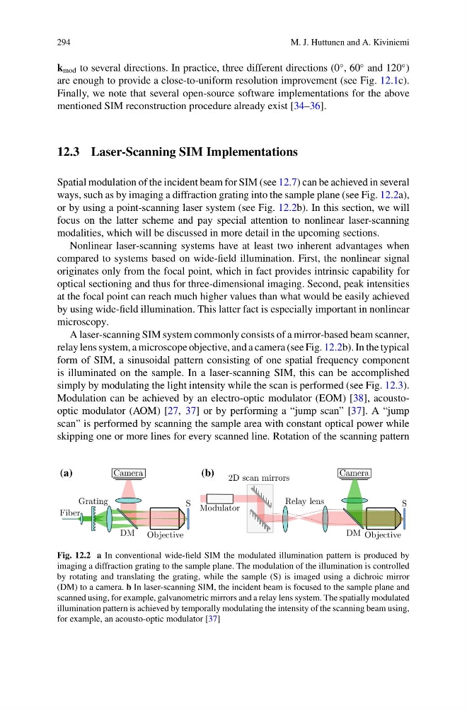
ways, such as by imaging a diffraction grating into the sample plane (see Fig. 12.2a),
or by using a point-scanning laser system (see Fig. 12.2b). In this section, we will
focus on the latter scheme and pay special attention to nonlinear laser-scanning
modalities, which will be discussed in more detail in the upcoming sections.
Nonlinear laser-scanning systems have at least two inherent advantages when
compared to systems based on wide-field illumination. First, the nonlinear signal
originates only from the focal point, which in fact provides intrinsic capability for
optical sectioning and thus for three-dimensional imaging. Second, peak intensities
at the focal point can reach much higher values than what would be easily achieved
by using wide-field illumination. This latter fact is especially important in nonlinear
microscopy.
A laser-scanning SIM system commonly consists of a mirror-based beam scanner,
relay lens system, a microscope objective, and a camera (see Fig. 12.2b). In the typical
form of SIM, a sinusoidal pattern consisting of one spatial frequency component
is illuminated on the sample. In a laser-scanning SIM, this can be accomplished
simply by modulating the light intensity while the scan is performed (see Fig. 12.3).
Modulation can be achieved by an electro-optic modulator (EOM) [38], acoustooptic modulator (AOM) [27, 37] or by performing a “jump scan” [37]. A “jump
scan” is performed by scanning the sample area with constant optical power while
skipping one or more lines for every scanned line. Rotation of the scanning pattern
(a)
(b)
Fig. 12.2 a In conventional wide-field SIM the modulated illumination pattern is produced by
imaging a diffraction grating to the sample plane. The modulation of the illumination is controlled
by rotating and translating the grating, while the sample (S) is imaged using a dichroic mirror
(DM) to a camera. b In laser-scanning SIM, the incident beam is focused to the sample plane and
scanned using, for example, galvanometric mirrors and a relay lens system. The spatially modulated
illumination pattern is achieved by temporally modulating the intensity of the scanning beam using,
for example, an acousto-optic modulator [37]
M. J. Huttunen and A. Kiviniemi
k mod to several directions. In practice, three different directions (0
◦ , 60
◦ and 120
◦ )
are enough to provide a close-to-uniform resolution improvement (see Fig. 12.1c).
Finally, we note that several open-source software implementations for the above
mentioned SIM reconstruction procedure already exist [34–36].
12.3 Laser-Scanning SIM Implementations
Spatial modulation of the incident beam for SIM (see 12.7) can be achieved in several
ways, such as by imaging a diffraction grating into the sample plane (see Fig. 12.2a),
or by using a point-scanning laser system (see Fig. 12.2b). In this section, we will
focus on the latter scheme and pay special attention to nonlinear laser-scanning
modalities, which will be discussed in more detail in the upcoming sections.
Nonlinear laser-scanning systems have at least two inherent advantages when
compared to systems based on wide-field illumination. First, the nonlinear signal
originates only from the focal point, which in fact provides intrinsic capability for
optical sectioning and thus for three-dimensional imaging. Second, peak intensities
at the focal point can reach much higher values than what would be easily achieved
by using wide-field illumination. This latter fact is especially important in nonlinear
microscopy.
A laser-scanning SIM system commonly consists of a mirror-based beam scanner,
relay lens system, a microscope objective, and a camera (see Fig. 12.2b). In the typical
form of SIM, a sinusoidal pattern consisting of one spatial frequency component
is illuminated on the sample. In a laser-scanning SIM, this can be accomplished
simply by modulating the light intensity while the scan is performed (see Fig. 12.3).
Modulation can be achieved by an electro-optic modulator (EOM) [38], acoustooptic modulator (AOM) [27, 37] or by performing a “jump scan” [37]. A “jump
scan” is performed by scanning the sample area with constant optical power while
skipping one or more lines for every scanned line. Rotation of the scanning pattern
(a)
(b)
Fig. 12.2 a In conventional wide-field SIM the modulated illumination pattern is produced by
imaging a diffraction grating to the sample plane. The modulation of the illumination is controlled
by rotating and translating the grating, while the sample (S) is imaged using a dichroic mirror
(DM) to a camera. b In laser-scanning SIM, the incident beam is focused to the sample plane and
scanned using, for example, galvanometric mirrors and a relay lens system. The spatially modulated
illumination pattern is achieved by temporally modulating the intensity of the scanning beam using,
for example, an acousto-optic modulator [37]