

268
O. Tzang et al.
11.3 Experimental System
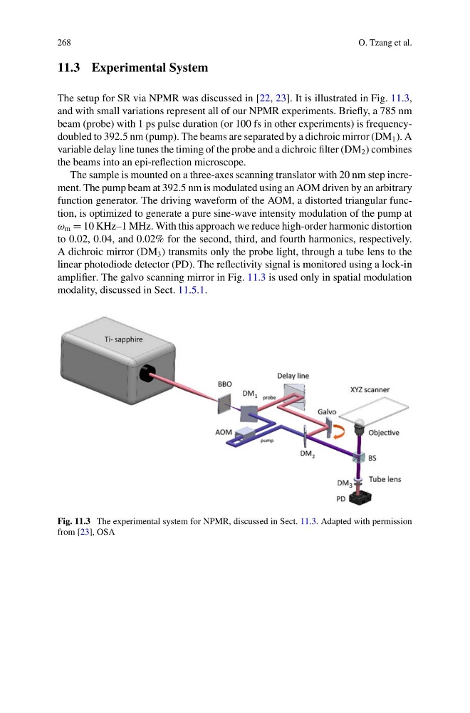
The setup for SR via NPMR was discussed in [22, 23]. It is illustrated in Fig. 11.3,
and with small variations represent all of our NPMR experiments. Briefly, a 785 nm
beam (probe) with 1 ps pulse duration (or 100 fs in other experiments) is frequencydoubled to 392.5 nm (pump). The beams are separated by a dichroic mirror (DM 1 ). A
variable delay line tunes the timing of the probe and a dichroic filter (DM 2 ) combines
the beams into an epi-reflection microscope.
The sample is mounted on a three-axes scanning translator with 20 nm step increment. The pump beam at 392.5 nm is modulated using an AOM driven by an arbitrary
function generator. The driving waveform of the AOM, a distorted triangular function, is optimized to generate a pure sine-wave intensity modulation of the pump at
ω m = 10 KHz–1 MHz. With this approach we reduce high-order harmonic distortion
to 0.02, 0.04, and 0.02% for the second, third, and fourth harmonics, respectively.
A dichroic mirror (DM 3 ) transmits only the probe light, through a tube lens to the
linear photodiode detector (PD). The reflectivity signal is monitored using a lock-in
amplifier. The galvo scanning mirror in Fig. 11.3 is used only in spatial modulation
modality, discussed in Sect. 11.5.1.
Fig. 11.3 The experimental system for NPMR, discussed in Sect. 11.3. Adapted with permission
from [23], OSA
O. Tzang et al.
11.3 Experimental System
The setup for SR via NPMR was discussed in [22, 23]. It is illustrated in Fig. 11.3,
and with small variations represent all of our NPMR experiments. Briefly, a 785 nm
beam (probe) with 1 ps pulse duration (or 100 fs in other experiments) is frequencydoubled to 392.5 nm (pump). The beams are separated by a dichroic mirror (DM 1 ). A
variable delay line tunes the timing of the probe and a dichroic filter (DM 2 ) combines
the beams into an epi-reflection microscope.
The sample is mounted on a three-axes scanning translator with 20 nm step increment. The pump beam at 392.5 nm is modulated using an AOM driven by an arbitrary
function generator. The driving waveform of the AOM, a distorted triangular function, is optimized to generate a pure sine-wave intensity modulation of the pump at
ω m = 10 KHz–1 MHz. With this approach we reduce high-order harmonic distortion
to 0.02, 0.04, and 0.02% for the second, third, and fourth harmonics, respectively.
A dichroic mirror (DM 3 ) transmits only the probe light, through a tube lens to the
linear photodiode detector (PD). The reflectivity signal is monitored using a lock-in
amplifier. The galvo scanning mirror in Fig. 11.3 is used only in spatial modulation
modality, discussed in Sect. 11.5.1.
Fig. 11.3 The experimental system for NPMR, discussed in Sect. 11.3. Adapted with permission
from [23], OSA