

230
H. Pinhas et al.
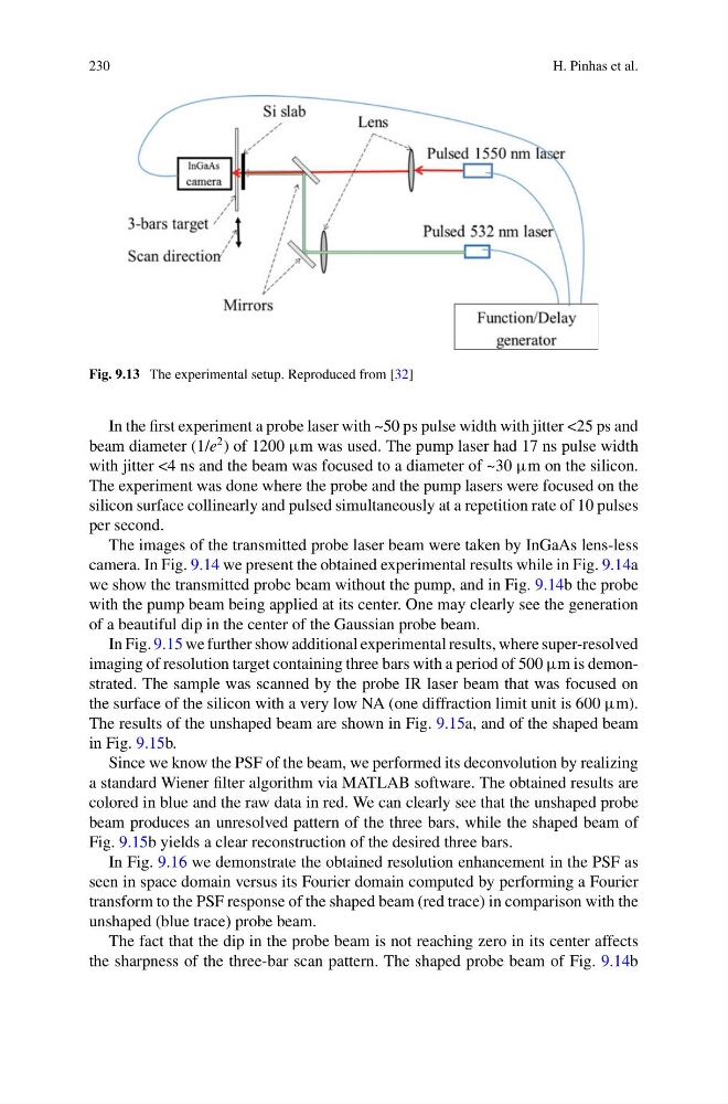
Fig. 9.13 The experimental setup. Reproduced from [32]
In the first experiment a probe laser with ~50 ps pulse width with jitter <25 ps and
beam diameter (1/e
2 ) of 1200 μm was used. The pump laser had 17 ns pulse width
with jitter <4 ns and the beam was focused to a diameter of ~30 μm on the silicon.
The experiment was done where the probe and the pump lasers were focused on the
silicon surface collinearly and pulsed simultaneously at a repetition rate of 10 pulses
per second.
The images of the transmitted probe laser beam were taken by InGaAs lens-less
camera. In Fig. 9.14 we present the obtained experimental results while in Fig. 9.14a
we show the transmitted probe beam without the pump, and in Fig. 9.14b the probe
with the pump beam being applied at its center. One may clearly see the generation
of a beautiful dip in the center of the Gaussian probe beam.
In Fig. 9.15 we further show additional experimental results, where super-resolved
imaging of resolution target containing three bars with a period of 500 μm is demonstrated. The sample was scanned by the probe IR laser beam that was focused on
the surface of the silicon with a very low NA (one diffraction limit unit is 600 μm).
The results of the unshaped beam are shown in Fig. 9.15a, and of the shaped beam
in Fig. 9.15b.
Since we know the PSF of the beam, we performed its deconvolution by realizing
a standard Wiener filter algorithm via MATLAB software. The obtained results are
colored in blue and the raw data in red. We can clearly see that the unshaped probe
beam produces an unresolved pattern of the three bars, while the shaped beam of
Fig. 9.15b yields a clear reconstruction of the desired three bars.
In Fig. 9.16 we demonstrate the obtained resolution enhancement in the PSF as
seen in space domain versus its Fourier domain computed by performing a Fourier
transform to the PSF response of the shaped beam (red trace) in comparison with the
unshaped (blue trace) probe beam.
The fact that the dip in the probe beam is not reaching zero in its center affects
the sharpness of the three-bar scan pattern. The shaped probe beam of Fig. 9.14b
H. Pinhas et al.
Fig. 9.13 The experimental setup. Reproduced from [32]
In the first experiment a probe laser with ~50 ps pulse width with jitter <25 ps and
beam diameter (1/e
2 ) of 1200 μm was used. The pump laser had 17 ns pulse width
with jitter <4 ns and the beam was focused to a diameter of ~30 μm on the silicon.
The experiment was done where the probe and the pump lasers were focused on the
silicon surface collinearly and pulsed simultaneously at a repetition rate of 10 pulses
per second.
The images of the transmitted probe laser beam were taken by InGaAs lens-less
camera. In Fig. 9.14 we present the obtained experimental results while in Fig. 9.14a
we show the transmitted probe beam without the pump, and in Fig. 9.14b the probe
with the pump beam being applied at its center. One may clearly see the generation
of a beautiful dip in the center of the Gaussian probe beam.
In Fig. 9.15 we further show additional experimental results, where super-resolved
imaging of resolution target containing three bars with a period of 500 μm is demonstrated. The sample was scanned by the probe IR laser beam that was focused on
the surface of the silicon with a very low NA (one diffraction limit unit is 600 μm).
The results of the unshaped beam are shown in Fig. 9.15a, and of the shaped beam
in Fig. 9.15b.
Since we know the PSF of the beam, we performed its deconvolution by realizing
a standard Wiener filter algorithm via MATLAB software. The obtained results are
colored in blue and the raw data in red. We can clearly see that the unshaped probe
beam produces an unresolved pattern of the three bars, while the shaped beam of
Fig. 9.15b yields a clear reconstruction of the desired three bars.
In Fig. 9.16 we demonstrate the obtained resolution enhancement in the PSF as
seen in space domain versus its Fourier domain computed by performing a Fourier
transform to the PSF response of the shaped beam (red trace) in comparison with the
unshaped (blue trace) probe beam.
The fact that the dip in the probe beam is not reaching zero in its center affects
the sharpness of the three-bar scan pattern. The shaped probe beam of Fig. 9.14b