

186
P. Bianchini et al.
one. The SFG technique presented in Sect. 7.2.1 can also be applied to achieve the
temporal overlap of the saturation pump pulses with the probe ones. In order to assure
optimal performances, the circular polarization of the doughnut beam [103] needs
to be maintained at the focal plane using a pair of half- and quarter-wave plates (λ/2
and λ/4, respectively). The saturation beam can be collinearly combined with the
pump beam with a beam combiner before the dichroic mirror of the probe beam (as
proposed in [100]), or it can be combined directly with both beams using a polarizing
beam splitter (PBS, as proposed in [54] and sketched in Fig. 7.5b).
Wang et al. [100] demonstrated this technique to image graphite nanoplatelets,
which are strong absorber and saturable materials. The suppression of the
pump–probe signal results is exponentially dependent on the saturation pump power
(I sat ), a behavior that is at the basis for achieving a reduction of the detection volume
below the diffraction limit (see Sect. 7.3.1). By fitting the depletion curve to the
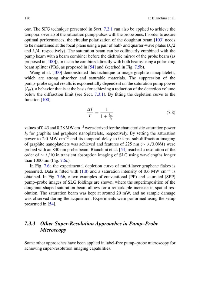
function [100]
ΔT
T
=
1
1 +
I sat
I 0
(7.8)
values of 0.43 and 0.28 MW cm
−2 were derived for the characteristic saturation power
I 0 for graphite and graphene nanoplatelets, respectively. By setting the saturation
power to 2.0 MW cm
−2 and its temporal delay to 0.4 ps, sub-diffraction imaging
of graphite nanoplatelets was achieved and features of 225 nm (∼ λ/3.0NA) were
probed with an 830 nm probe beam. Bianchini et al. [54] reached a resolution of the
order of ∼ λ/10 in transient absorption imaging of SLG using wavelengths longer
than 1000 nm (Fig. 7.6c).
In Fig. 7.6a the experimental depletion curve of multi-layer graphene flakes is
presented. Data is fitted with (1.8) and a saturation intensity of 0.6 MW cm
−2 is
obtained. In Fig. 7.6b, c two examples of conventional (PP) and saturated (SPP)
pump–probe images of SLG foldings are shown, where the superimposition of the
doughnut-shaped saturation beam allows for a remarkable increase in spatial resolution. The saturation beam was kept at around 20 mW, and no sample damage
was observed during the acquisition. Experiments were performed using the setup
presented in [54].
7.3.3 Other Super-Resolution Approaches in Pump–Probe
Microscopy
Some other approaches have been applied in label-free pump–probe microscopy for
achieving super-resolution imaging capabilities.
P. Bianchini et al.
one. The SFG technique presented in Sect. 7.2.1 can also be applied to achieve the
temporal overlap of the saturation pump pulses with the probe ones. In order to assure
optimal performances, the circular polarization of the doughnut beam [103] needs
to be maintained at the focal plane using a pair of half- and quarter-wave plates (λ/2
and λ/4, respectively). The saturation beam can be collinearly combined with the
pump beam with a beam combiner before the dichroic mirror of the probe beam (as
proposed in [100]), or it can be combined directly with both beams using a polarizing
beam splitter (PBS, as proposed in [54] and sketched in Fig. 7.5b).
Wang et al. [100] demonstrated this technique to image graphite nanoplatelets,
which are strong absorber and saturable materials. The suppression of the
pump–probe signal results is exponentially dependent on the saturation pump power
(I sat ), a behavior that is at the basis for achieving a reduction of the detection volume
below the diffraction limit (see Sect. 7.3.1). By fitting the depletion curve to the
function [100]
ΔT
T
=
1
1 +
I sat
I 0
(7.8)
values of 0.43 and 0.28 MW cm
−2 were derived for the characteristic saturation power
I 0 for graphite and graphene nanoplatelets, respectively. By setting the saturation
power to 2.0 MW cm
−2 and its temporal delay to 0.4 ps, sub-diffraction imaging
of graphite nanoplatelets was achieved and features of 225 nm (∼ λ/3.0NA) were
probed with an 830 nm probe beam. Bianchini et al. [54] reached a resolution of the
order of ∼ λ/10 in transient absorption imaging of SLG using wavelengths longer
than 1000 nm (Fig. 7.6c).
In Fig. 7.6a the experimental depletion curve of multi-layer graphene flakes is
presented. Data is fitted with (1.8) and a saturation intensity of 0.6 MW cm
−2 is
obtained. In Fig. 7.6b, c two examples of conventional (PP) and saturated (SPP)
pump–probe images of SLG foldings are shown, where the superimposition of the
doughnut-shaped saturation beam allows for a remarkable increase in spatial resolution. The saturation beam was kept at around 20 mW, and no sample damage
was observed during the acquisition. Experiments were performed using the setup
presented in [54].
7.3.3 Other Super-Resolution Approaches in Pump–Probe
Microscopy
Some other approaches have been applied in label-free pump–probe microscopy for
achieving super-resolution imaging capabilities.