

7 Label-Free Pump–Probe Nanoscopy
185
approach was proposed by Bianchini et al. [54]. This absorption–saturation approach
is based on the collinear superimposition, in a conventional two-beam pump–probe
configuration (presented in Sect. 7.2.1), of a high-intensity non-modulated doughnutshaped pump beam, whose purpose is to transiently saturate the absorption at the
periphery of the focal spot. The saturation prevents the absorption of the probe
beam, which will be transmitted without any modulation, while the probe intensity
variation induced by the absorption of the modulated pump will be detected only
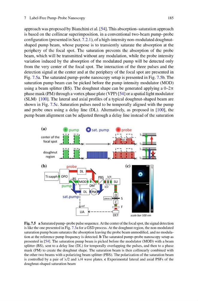
from the very center of the focal spot. The interaction of the three pulses and the
detection signal at the center and at the periphery of the focal spot are presented in
Fig. 7.5a. The saturated pump–probe nanoscopy setup is presented in Fig. 7.5b. The
saturation pump beam can be picked before the pump intensity modulator (MOD)
using a beam splitter (BS). The doughnut shape can be generated applying a 0–2π
phase mask (PM) through a vortex phase plate (VPP) [54] or a spatial light modulator
(SLM) [100]. The lateral and axial profiles of a typical doughnut-shaped beam are
shown in Fig. 7.5c. Saturation pulses need to be temporally aligned with the pump
and probe ones using a delay line (DL). Alternatively, as proposed in [100], the
pump beam alignment can be adjusted through a delay line instead of the saturation
Fig. 7.5 a Saturated pump–probe pulse sequence. At the center of the focal spot, the signal detection
is like the one presented in Fig. 7.3a for a GSD process. At the doughnut region, the non-modulated
saturation pump beam saturates the absorption leaving the probe beam unmodified, and no modulation at the reference pump frequency is detected. b The saturated pump–probe nanoscopy setup as
presented in [54]. The saturation pump beam is picked before the modulator (MOD) with a beam
splitter (BS), sent to a delay line (DL) for temporally overlapping the pulses, and then to a phase
mask (PM) to create the doughnut shape. The saturation beam is then collinearly combined with
the other two beams with a polarizing beam splitter (PBS). The polarization of the saturation beam
is controlled by a pair of λ/2 and λ/4 wave plates. c Experimental lateral and axial PSFs of the
doughnut-shaped saturation beam
185
approach was proposed by Bianchini et al. [54]. This absorption–saturation approach
is based on the collinear superimposition, in a conventional two-beam pump–probe
configuration (presented in Sect. 7.2.1), of a high-intensity non-modulated doughnutshaped pump beam, whose purpose is to transiently saturate the absorption at the
periphery of the focal spot. The saturation prevents the absorption of the probe
beam, which will be transmitted without any modulation, while the probe intensity
variation induced by the absorption of the modulated pump will be detected only
from the very center of the focal spot. The interaction of the three pulses and the
detection signal at the center and at the periphery of the focal spot are presented in
Fig. 7.5a. The saturated pump–probe nanoscopy setup is presented in Fig. 7.5b. The
saturation pump beam can be picked before the pump intensity modulator (MOD)
using a beam splitter (BS). The doughnut shape can be generated applying a 0–2π
phase mask (PM) through a vortex phase plate (VPP) [54] or a spatial light modulator
(SLM) [100]. The lateral and axial profiles of a typical doughnut-shaped beam are
shown in Fig. 7.5c. Saturation pulses need to be temporally aligned with the pump
and probe ones using a delay line (DL). Alternatively, as proposed in [100], the
pump beam alignment can be adjusted through a delay line instead of the saturation
Fig. 7.5 a Saturated pump–probe pulse sequence. At the center of the focal spot, the signal detection
is like the one presented in Fig. 7.3a for a GSD process. At the doughnut region, the non-modulated
saturation pump beam saturates the absorption leaving the probe beam unmodified, and no modulation at the reference pump frequency is detected. b The saturated pump–probe nanoscopy setup as
presented in [54]. The saturation pump beam is picked before the modulator (MOD) with a beam
splitter (BS), sent to a delay line (DL) for temporally overlapping the pulses, and then to a phase
mask (PM) to create the doughnut shape. The saturation beam is then collinearly combined with
the other two beams with a polarizing beam splitter (PBS). The polarization of the saturation beam
is controlled by a pair of λ/2 and λ/4 wave plates. c Experimental lateral and axial PSFs of the
doughnut-shaped saturation beam