

100
B. Simon and O. Haeberlé
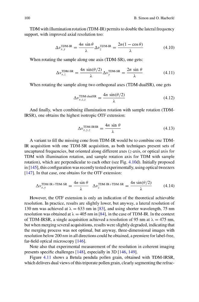
TDM with illumination rotation (TDM-IR) permits to double the lateral frequency
support, with improved axial resolution too:
v
TDM-IR
x,y
=
4n sin θ
λ
v
TDM-IR
z
=
2n(1 − cos θ)
λ
(4.10)
When rotating the sample along one axis (TDM-SR), one gets:
v
TDM-SR
x,z
=
4n sin(θ/2)
λ
v
TDM-SR
y
=
2n sin θ
λ
(4.11)
When rotating the sample along two orthogonal axes (TDM-dualSR), one gets
v
TDM-dualSR
x,z,z
=
4n sin(θ/2)
λ
(4.12)
And finally, when combining illumination rotation with sample rotation (TDMIRSR), one obtains the highest isotropic OTF extension:
v
TDM-IRSR
x,y,z
=
4n sin θ
λ
(4.13)
A variant to fill the missing cone from TDM-IR would be to combine one TDMIR acquisition with one TDM-SR acquisition, as both techniques present sets of
uncaptured frequencies, but oriented along different axes (z-axis, or optical axis for
TDM with illumination rotation, and sample rotation axis for TDM with sample
rotation), which are perpendicular to each other (see Fig. 4.10d). Initially proposed
in [145], this configuration was recently tested experimentally, using optical tweezers
[147]. In that case, one obtains for the OTF extension:
v
TDM-IR+TDM-SR
x,y
=
4n sin θ
λ
v
TDM-IR+TDM-SR
z
=
4n sin(θ/2)
λ
(4.14)
However, the OTF extension is only an indication of the theoretical achievable
resolution. In practice, results are slightly lower, but anyway, a lateral resolution of
130 nm was achieved at λ = 633 nm in [83], and using shorter wavelength, 75 nm
resolution was obtained at λ = 405 nm in [84], in the case of TDM-IR. In the context
of TDM-IRSR, a single acquisition achieved a resolution of 95 nm at λ = 475 nm,
but when merging several acquisitions, results were slightly degraded, indicating that
the merging process was not optimal, but anyway, three-dimensional images with
resolution below 200 nm in all directions could be obtained, a premiere for label-free,
far-field optical microscopy [146].
Note also that experimental measurement of the resolution in coherent imaging
presents specific challenges [148], especially in 3D [146, 149].
Figure 4.11 shows a Betula pendula pollen grain, obtained with TDM-IRSR,
which delivers dual views of this triporate pollen grain, clearly segmenting the refrac-
B. Simon and O. Haeberlé
TDM with illumination rotation (TDM-IR) permits to double the lateral frequency
support, with improved axial resolution too:
v
TDM-IR
x,y
=
4n sin θ
λ
v
TDM-IR
z
=
2n(1 − cos θ)
λ
(4.10)
When rotating the sample along one axis (TDM-SR), one gets:
v
TDM-SR
x,z
=
4n sin(θ/2)
λ
v
TDM-SR
y
=
2n sin θ
λ
(4.11)
When rotating the sample along two orthogonal axes (TDM-dualSR), one gets
v
TDM-dualSR
x,z,z
=
4n sin(θ/2)
λ
(4.12)
And finally, when combining illumination rotation with sample rotation (TDMIRSR), one obtains the highest isotropic OTF extension:
v
TDM-IRSR
x,y,z
=
4n sin θ
λ
(4.13)
A variant to fill the missing cone from TDM-IR would be to combine one TDMIR acquisition with one TDM-SR acquisition, as both techniques present sets of
uncaptured frequencies, but oriented along different axes (z-axis, or optical axis for
TDM with illumination rotation, and sample rotation axis for TDM with sample
rotation), which are perpendicular to each other (see Fig. 4.10d). Initially proposed
in [145], this configuration was recently tested experimentally, using optical tweezers
[147]. In that case, one obtains for the OTF extension:
v
TDM-IR+TDM-SR
x,y
=
4n sin θ
λ
v
TDM-IR+TDM-SR
z
=
4n sin(θ/2)
λ
(4.14)
However, the OTF extension is only an indication of the theoretical achievable
resolution. In practice, results are slightly lower, but anyway, a lateral resolution of
130 nm was achieved at λ = 633 nm in [83], and using shorter wavelength, 75 nm
resolution was obtained at λ = 405 nm in [84], in the case of TDM-IR. In the context
of TDM-IRSR, a single acquisition achieved a resolution of 95 nm at λ = 475 nm,
but when merging several acquisitions, results were slightly degraded, indicating that
the merging process was not optimal, but anyway, three-dimensional images with
resolution below 200 nm in all directions could be obtained, a premiere for label-free,
far-field optical microscopy [146].
Note also that experimental measurement of the resolution in coherent imaging
presents specific challenges [148], especially in 3D [146, 149].
Figure 4.11 shows a Betula pendula pollen grain, obtained with TDM-IRSR,
which delivers dual views of this triporate pollen grain, clearly segmenting the refrac-