

12 Intra-operative Measurement of Brain Deformation
311
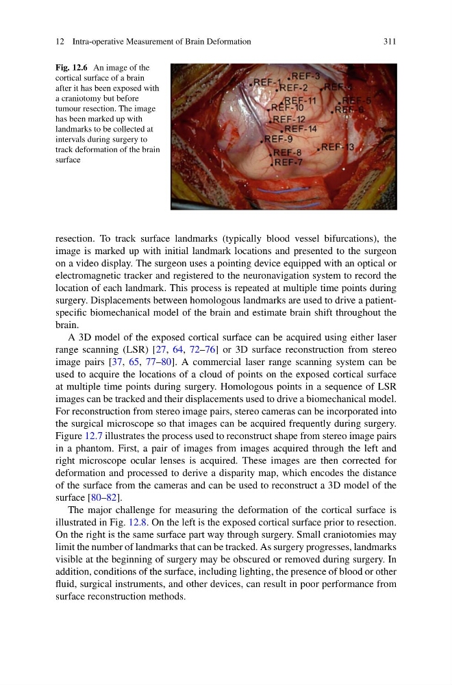
Fig. 12.6 An image of the
cortical surface of a brain
after it has been exposed with
a craniotomy but before
tumour resection. The image
has been marked up with
landmarks to be collected at
intervals during surgery to
track deformation of the brain
surface
resection. To track surface landmarks (typically blood vessel bifurcations), the
image is marked up with initial landmark locations and presented to the surgeon
on a video display. The surgeon uses a pointing device equipped with an optical or
electromagnetic tracker and registered to the neuronavigation system to record the
location of each landmark. This process is repeated at multiple time points during
surgery. Displacements between homologous landmarks are used to drive a patientspecific biomechanical model of the brain and estimate brain shift throughout the
brain.
A 3D model of the exposed cortical surface can be acquired using either laser
range scanning (LSR) [27, 64, 72–76] or 3D surface reconstruction from stereo
image pairs [37, 65, 77–80]. A commercial laser range scanning system can be
used to acquire the locations of a cloud of points on the exposed cortical surface
at multiple time points during surgery. Homologous points in a sequence of LSR
images can be tracked and their displacements used to drive a biomechanical model.
For reconstruction from stereo image pairs, stereo cameras can be incorporated into
the surgical microscope so that images can be acquired frequently during surgery.
Figure 12.7 illustrates the process used to reconstruct shape from stereo image pairs
in a phantom. First, a pair of images from images acquired through the left and
right microscope ocular lenses is acquired. These images are then corrected for
deformation and processed to derive a disparity map, which encodes the distance
of the surface from the cameras and can be used to reconstruct a 3D model of the
surface [80–82].
The major challenge for measuring the deformation of the cortical surface is
illustrated in Fig. 12.8. On the left is the exposed cortical surface prior to resection.
On the right is the same surface part way through surgery. Small craniotomies may
limit the number of landmarks that can be tracked. As surgery progresses, landmarks
visible at the beginning of surgery may be obscured or removed during surgery. In
addition, conditions of the surface, including lighting, the presence of blood or other
fluid, surgical instruments, and other devices, can result in poor performance from
surface reconstruction methods.
311
Fig. 12.6 An image of the
cortical surface of a brain
after it has been exposed with
a craniotomy but before
tumour resection. The image
has been marked up with
landmarks to be collected at
intervals during surgery to
track deformation of the brain
surface
resection. To track surface landmarks (typically blood vessel bifurcations), the
image is marked up with initial landmark locations and presented to the surgeon
on a video display. The surgeon uses a pointing device equipped with an optical or
electromagnetic tracker and registered to the neuronavigation system to record the
location of each landmark. This process is repeated at multiple time points during
surgery. Displacements between homologous landmarks are used to drive a patientspecific biomechanical model of the brain and estimate brain shift throughout the
brain.
A 3D model of the exposed cortical surface can be acquired using either laser
range scanning (LSR) [27, 64, 72–76] or 3D surface reconstruction from stereo
image pairs [37, 65, 77–80]. A commercial laser range scanning system can be
used to acquire the locations of a cloud of points on the exposed cortical surface
at multiple time points during surgery. Homologous points in a sequence of LSR
images can be tracked and their displacements used to drive a biomechanical model.
For reconstruction from stereo image pairs, stereo cameras can be incorporated into
the surgical microscope so that images can be acquired frequently during surgery.
Figure 12.7 illustrates the process used to reconstruct shape from stereo image pairs
in a phantom. First, a pair of images from images acquired through the left and
right microscope ocular lenses is acquired. These images are then corrected for
deformation and processed to derive a disparity map, which encodes the distance
of the surface from the cameras and can be used to reconstruct a 3D model of the
surface [80–82].
The major challenge for measuring the deformation of the cortical surface is
illustrated in Fig. 12.8. On the left is the exposed cortical surface prior to resection.
On the right is the same surface part way through surgery. Small craniotomies may
limit the number of landmarks that can be tracked. As surgery progresses, landmarks
visible at the beginning of surgery may be obscured or removed during surgery. In
addition, conditions of the surface, including lighting, the presence of blood or other
fluid, surgical instruments, and other devices, can result in poor performance from
surface reconstruction methods.