

10 Finite Element Algorithms for Computational Biomechanics of the Brain
263
0.2
0.18
0.16
0.14
0.12
0.1
0.08
0.06
0.04
0.02
0
0.18
0.16
0.14
0.12
0.1
0.08
0.06
0.04
0.02
0
0.18
2
1.5
1.5
0.5
0.5
0
0
1
1
2
3
1.5
2.5
3.5
0.5
0
1
0.16
0.14
0.12
0.1
0.08
0.06
0.04
0.02
0
0.15
0.05
-0.05
a)
c)
d)
b)
0.05
y [m]
[m]
[m]
[m]
z [m]
0.1
0
0
-0.05
0.1
0.05
0
[m]
-0.05
0.1
0.05
0
[m]
-0.05
0.1
0.05
0
[m]
0.1
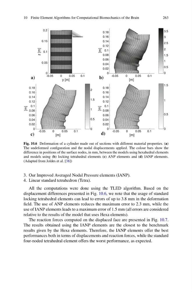
Fig. 10.6 Deformation of a cylinder made out of sections with different material properties. (a)
The undeformed configuration and the nodal displacements applied. The colour bars show the
difference in positions of the surface nodes, in mm, between the models using hexahedral elements
and models using (b) locking tetrahedral elements (c) ANP elements and (d) IANP elements.
(Adapted from Joldes et al. [38])
3. Our Improved Averaged Nodal Pressure elements (IANP).
4. Linear standard tetrahedron (Tetra).
All the computations were done using the TLED algorithm. Based on the
displacement differences presented in Fig. 10.6, we note that the usage of standard
locking tetrahedral elements can lead to errors of up to 3.8 mm in the deformation
field. The use of ANP elements reduces the maximum error to 2.3 mm, while the
use of IANP elements leads to a maximum error of 1.5 mm (all errors are considered
relative to the results of the model that uses Hexa elements).
The reaction forces computed on the displaced face are presented in Fig. 10.7.
The results obtained using the IANP elements are the closest to the benchmark
results given by the Hexa elements. Therefore, the IANP elements offer the best
performances both in terms of displacements and reaction forces, while the standard
four-noded tetrahedral element offers the worst performance, as expected.
263
0.2
0.18
0.16
0.14
0.12
0.1
0.08
0.06
0.04
0.02
0
0.18
0.16
0.14
0.12
0.1
0.08
0.06
0.04
0.02
0
0.18
2
1.5
1.5
0.5
0.5
0
0
1
1
2
3
1.5
2.5
3.5
0.5
0
1
0.16
0.14
0.12
0.1
0.08
0.06
0.04
0.02
0
0.15
0.05
-0.05
a)
c)
d)
b)
0.05
y [m]
[m]
[m]
[m]
z [m]
0.1
0
0
-0.05
0.1
0.05
0
[m]
-0.05
0.1
0.05
0
[m]
-0.05
0.1
0.05
0
[m]
0.1
Fig. 10.6 Deformation of a cylinder made out of sections with different material properties. (a)
The undeformed configuration and the nodal displacements applied. The colour bars show the
difference in positions of the surface nodes, in mm, between the models using hexahedral elements
and models using (b) locking tetrahedral elements (c) ANP elements and (d) IANP elements.
(Adapted from Joldes et al. [38])
3. Our Improved Averaged Nodal Pressure elements (IANP).
4. Linear standard tetrahedron (Tetra).
All the computations were done using the TLED algorithm. Based on the
displacement differences presented in Fig. 10.6, we note that the usage of standard
locking tetrahedral elements can lead to errors of up to 3.8 mm in the deformation
field. The use of ANP elements reduces the maximum error to 2.3 mm, while the
use of IANP elements leads to a maximum error of 1.5 mm (all errors are considered
relative to the results of the model that uses Hexa elements).
The reaction forces computed on the displaced face are presented in Fig. 10.7.
The results obtained using the IANP elements are the closest to the benchmark
results given by the Hexa elements. Therefore, the IANP elements offer the best
performances both in terms of displacements and reaction forces, while the standard
four-noded tetrahedral element offers the worst performance, as expected.