

9 Modelling of Cerebrospinal Fluid Flow by Computational Fluid Dynamics
219
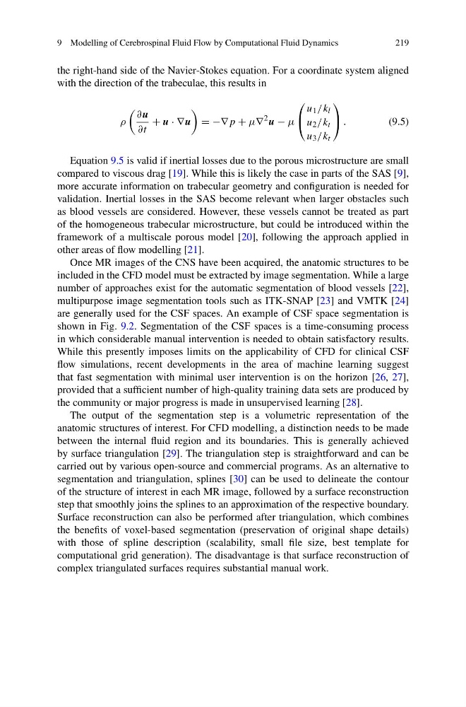
the right-hand side of the Navier-Stokes equation. For a coordinate system aligned
with the direction of the trabeculae, this results in
ρ
∂u
∂t
+ u · ∇u
= −∇p + μ∇
2 u − μ
⎛
⎝
u 1 /k l
u 2 /k t
u 3 /k t
⎞
⎠ .
(9.5)
Equation 9.5 is valid if inertial losses due to the porous microstructure are small
compared to viscous drag [19]. While this is likely the case in parts of the SAS [9],
more accurate information on trabecular geometry and configuration is needed for
validation. Inertial losses in the SAS become relevant when larger obstacles such
as blood vessels are considered. However, these vessels cannot be treated as part
of the homogeneous trabecular microstructure, but could be introduced within the
framework of a multiscale porous model [20], following the approach applied in
other areas of flow modelling [21].
Once MR images of the CNS have been acquired, the anatomic structures to be
included in the CFD model must be extracted by image segmentation. While a large
number of approaches exist for the automatic segmentation of blood vessels [22],
multipurpose image segmentation tools such as ITK-SNAP [23] and VMTK [24]
are generally used for the CSF spaces. An example of CSF space segmentation is
shown in Fig. 9.2. Segmentation of the CSF spaces is a time-consuming process
in which considerable manual intervention is needed to obtain satisfactory results.
While this presently imposes limits on the applicability of CFD for clinical CSF
flow simulations, recent developments in the area of machine learning suggest
that fast segmentation with minimal user intervention is on the horizon [26, 27],
provided that a sufficient number of high-quality training data sets are produced by
the community or major progress is made in unsupervised learning [28].
The output of the segmentation step is a volumetric representation of the
anatomic structures of interest. For CFD modelling, a distinction needs to be made
between the internal fluid region and its boundaries. This is generally achieved
by surface triangulation [29]. The triangulation step is straightforward and can be
carried out by various open-source and commercial programs. As an alternative to
segmentation and triangulation, splines [30] can be used to delineate the contour
of the structure of interest in each MR image, followed by a surface reconstruction
step that smoothly joins the splines to an approximation of the respective boundary.
Surface reconstruction can also be performed after triangulation, which combines
the benefits of voxel-based segmentation (preservation of original shape details)
with those of spline description (scalability, small file size, best template for
computational grid generation). The disadvantage is that surface reconstruction of
complex triangulated surfaces requires substantial manual work.
219
the right-hand side of the Navier-Stokes equation. For a coordinate system aligned
with the direction of the trabeculae, this results in
ρ
∂u
∂t
+ u · ∇u
= −∇p + μ∇
2 u − μ
⎛
⎝
u 1 /k l
u 2 /k t
u 3 /k t
⎞
⎠ .
(9.5)
Equation 9.5 is valid if inertial losses due to the porous microstructure are small
compared to viscous drag [19]. While this is likely the case in parts of the SAS [9],
more accurate information on trabecular geometry and configuration is needed for
validation. Inertial losses in the SAS become relevant when larger obstacles such
as blood vessels are considered. However, these vessels cannot be treated as part
of the homogeneous trabecular microstructure, but could be introduced within the
framework of a multiscale porous model [20], following the approach applied in
other areas of flow modelling [21].
Once MR images of the CNS have been acquired, the anatomic structures to be
included in the CFD model must be extracted by image segmentation. While a large
number of approaches exist for the automatic segmentation of blood vessels [22],
multipurpose image segmentation tools such as ITK-SNAP [23] and VMTK [24]
are generally used for the CSF spaces. An example of CSF space segmentation is
shown in Fig. 9.2. Segmentation of the CSF spaces is a time-consuming process
in which considerable manual intervention is needed to obtain satisfactory results.
While this presently imposes limits on the applicability of CFD for clinical CSF
flow simulations, recent developments in the area of machine learning suggest
that fast segmentation with minimal user intervention is on the horizon [26, 27],
provided that a sufficient number of high-quality training data sets are produced by
the community or major progress is made in unsupervised learning [28].
The output of the segmentation step is a volumetric representation of the
anatomic structures of interest. For CFD modelling, a distinction needs to be made
between the internal fluid region and its boundaries. This is generally achieved
by surface triangulation [29]. The triangulation step is straightforward and can be
carried out by various open-source and commercial programs. As an alternative to
segmentation and triangulation, splines [30] can be used to delineate the contour
of the structure of interest in each MR image, followed by a surface reconstruction
step that smoothly joins the splines to an approximation of the respective boundary.
Surface reconstruction can also be performed after triangulation, which combines
the benefits of voxel-based segmentation (preservation of original shape details)
with those of spline description (scalability, small file size, best template for
computational grid generation). The disadvantage is that surface reconstruction of
complex triangulated surfaces requires substantial manual work.