

114
K. H. Yang and H. Mao
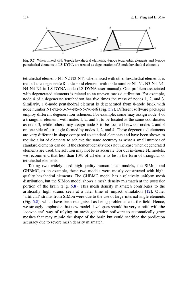
Fig. 5.7 When mixed with 8-node hexahedral elements, 4-node tetrahedral elements and 6-node
pentahedral elements in LS-DYNA are treated as degeneration of 8-node hexahedral elements
tetrahedral element (N1-N2-N3-N4), when mixed with other hexahedral elements, is
treated as a degenerate 8-node solid element with node number N1-N2-N3-N4-N4N4-N4-N4 in LS-DYNA code (LS-DYNA user manual). One problem associated
with degenerated elements is related to an uneven mass distribution. For example,
node 4 of a degenerate tetrahedron has five times the mass of nodes 1, 2, and 3.
Similarly, a 6-node pentahedral element is degenerated from 8-node brick with
node number N1-N2-N3-N4-N5-N5-N6-N6 (Fig. 5.7). Different software packages
employ different degeneration schemes. For example, some may assign node 4 of
a triangular element, with nodes 1, 2, and 3, to be located at the same coordinates
as node 3, while others may assign node 3 to be located between nodes 2 and 4
on one side of a triangle formed by nodes 1, 2, and 4. These degenerated elements
are very different in shape compared to standard elements and have been shown to
require a lot of elements to achieve the same accuracy as what a small number of
standard elements can do. If the element density does not increase when degenerated
elements are used, the solution may not be as accurate. For our in-house FE models,
we recommend that less than 10% of all elements be in the form of triangular or
tetrahedral elements.
Taking two widely used high-quality human head models, the SIMon and
GHBMC, as an example, these two models were mostly constructed with highquality hexahedral elements. The GHBMC model has a relatively uniform mesh
distribution, but the SIMon model shows a mesh density mismatch at the posterior
portion of the brain (Fig. 5.8). This mesh density mismatch contributes to the
artificially high strains seen at a later time of impact simulation [12]. Other
‘artificial’ strains from SIMon were due to the use of large-internal-angle elements
(Fig. 5.8), which have been recognised as being problematic in the field. Hence,
we strongly emphasise that new model developers should be very careful with the
‘convenient’ way of relying on mesh generation software to automatically grow
meshes that may mimic the shape of the brain but could sacrifice the prediction
accuracy due to severe mesh density mismatch.
K. H. Yang and H. Mao
Fig. 5.7 When mixed with 8-node hexahedral elements, 4-node tetrahedral elements and 6-node
pentahedral elements in LS-DYNA are treated as degeneration of 8-node hexahedral elements
tetrahedral element (N1-N2-N3-N4), when mixed with other hexahedral elements, is
treated as a degenerate 8-node solid element with node number N1-N2-N3-N4-N4N4-N4-N4 in LS-DYNA code (LS-DYNA user manual). One problem associated
with degenerated elements is related to an uneven mass distribution. For example,
node 4 of a degenerate tetrahedron has five times the mass of nodes 1, 2, and 3.
Similarly, a 6-node pentahedral element is degenerated from 8-node brick with
node number N1-N2-N3-N4-N5-N5-N6-N6 (Fig. 5.7). Different software packages
employ different degeneration schemes. For example, some may assign node 4 of
a triangular element, with nodes 1, 2, and 3, to be located at the same coordinates
as node 3, while others may assign node 3 to be located between nodes 2 and 4
on one side of a triangle formed by nodes 1, 2, and 4. These degenerated elements
are very different in shape compared to standard elements and have been shown to
require a lot of elements to achieve the same accuracy as what a small number of
standard elements can do. If the element density does not increase when degenerated
elements are used, the solution may not be as accurate. For our in-house FE models,
we recommend that less than 10% of all elements be in the form of triangular or
tetrahedral elements.
Taking two widely used high-quality human head models, the SIMon and
GHBMC, as an example, these two models were mostly constructed with highquality hexahedral elements. The GHBMC model has a relatively uniform mesh
distribution, but the SIMon model shows a mesh density mismatch at the posterior
portion of the brain (Fig. 5.8). This mesh density mismatch contributes to the
artificially high strains seen at a later time of impact simulation [12]. Other
‘artificial’ strains from SIMon were due to the use of large-internal-angle elements
(Fig. 5.8), which have been recognised as being problematic in the field. Hence,
we strongly emphasise that new model developers should be very careful with the
‘convenient’ way of relying on mesh generation software to automatically grow
meshes that may mimic the shape of the brain but could sacrifice the prediction
accuracy due to severe mesh density mismatch.