

112
K. H. Yang and H. Mao
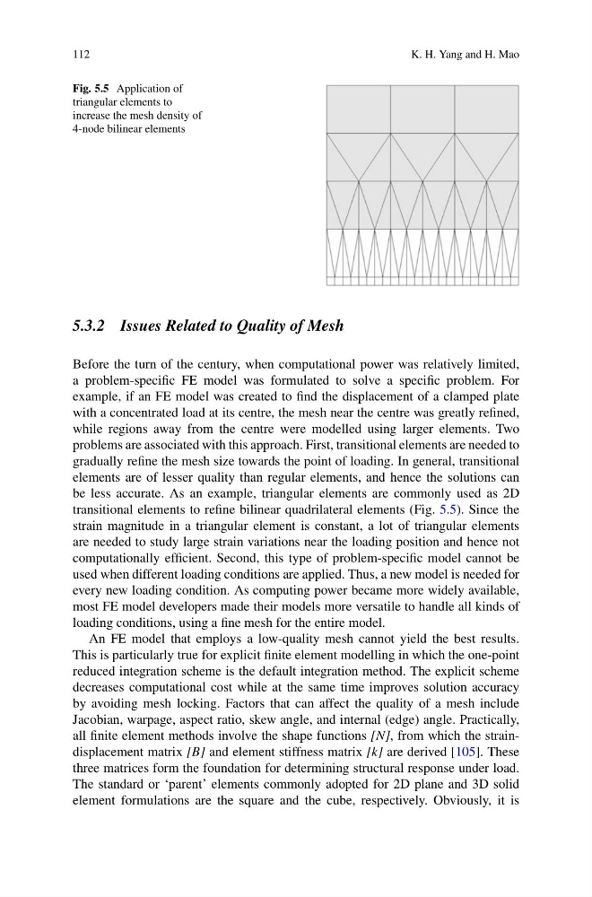
Fig. 5.5 Application of
triangular elements to
increase the mesh density of
4-node bilinear elements
5.3.2 Issues Related to Quality of Mesh
Before the turn of the century, when computational power was relatively limited,
a problem-specific FE model was formulated to solve a specific problem. For
example, if an FE model was created to find the displacement of a clamped plate
with a concentrated load at its centre, the mesh near the centre was greatly refined,
while regions away from the centre were modelled using larger elements. Two
problems are associated with this approach. First, transitional elements are needed to
gradually refine the mesh size towards the point of loading. In general, transitional
elements are of lesser quality than regular elements, and hence the solutions can
be less accurate. As an example, triangular elements are commonly used as 2D
transitional elements to refine bilinear quadrilateral elements (Fig. 5.5). Since the
strain magnitude in a triangular element is constant, a lot of triangular elements
are needed to study large strain variations near the loading position and hence not
computationally efficient. Second, this type of problem-specific model cannot be
used when different loading conditions are applied. Thus, a new model is needed for
every new loading condition. As computing power became more widely available,
most FE model developers made their models more versatile to handle all kinds of
loading conditions, using a fine mesh for the entire model.
An FE model that employs a low-quality mesh cannot yield the best results.
This is particularly true for explicit finite element modelling in which the one-point
reduced integration scheme is the default integration method. The explicit scheme
decreases computational cost while at the same time improves solution accuracy
by avoiding mesh locking. Factors that can affect the quality of a mesh include
Jacobian, warpage, aspect ratio, skew angle, and internal (edge) angle. Practically,
all finite element methods involve the shape functions [N], from which the straindisplacement matrix [B] and element stiffness matrix [k] are derived [105]. These
three matrices form the foundation for determining structural response under load.
The standard or ‘parent’ elements commonly adopted for 2D plane and 3D solid
element formulations are the square and the cube, respectively. Obviously, it is
K. H. Yang and H. Mao
Fig. 5.5 Application of
triangular elements to
increase the mesh density of
4-node bilinear elements
5.3.2 Issues Related to Quality of Mesh
Before the turn of the century, when computational power was relatively limited,
a problem-specific FE model was formulated to solve a specific problem. For
example, if an FE model was created to find the displacement of a clamped plate
with a concentrated load at its centre, the mesh near the centre was greatly refined,
while regions away from the centre were modelled using larger elements. Two
problems are associated with this approach. First, transitional elements are needed to
gradually refine the mesh size towards the point of loading. In general, transitional
elements are of lesser quality than regular elements, and hence the solutions can
be less accurate. As an example, triangular elements are commonly used as 2D
transitional elements to refine bilinear quadrilateral elements (Fig. 5.5). Since the
strain magnitude in a triangular element is constant, a lot of triangular elements
are needed to study large strain variations near the loading position and hence not
computationally efficient. Second, this type of problem-specific model cannot be
used when different loading conditions are applied. Thus, a new model is needed for
every new loading condition. As computing power became more widely available,
most FE model developers made their models more versatile to handle all kinds of
loading conditions, using a fine mesh for the entire model.
An FE model that employs a low-quality mesh cannot yield the best results.
This is particularly true for explicit finite element modelling in which the one-point
reduced integration scheme is the default integration method. The explicit scheme
decreases computational cost while at the same time improves solution accuracy
by avoiding mesh locking. Factors that can affect the quality of a mesh include
Jacobian, warpage, aspect ratio, skew angle, and internal (edge) angle. Practically,
all finite element methods involve the shape functions [N], from which the straindisplacement matrix [B] and element stiffness matrix [k] are derived [105]. These
three matrices form the foundation for determining structural response under load.
The standard or ‘parent’ elements commonly adopted for 2D plane and 3D solid
element formulations are the square and the cube, respectively. Obviously, it is