

– Pseudo-closed circuit used for water circulation (if contaminated, wastewater
outflow can be easily recovered by a pumping system)
– Hydraulic gradients significantly increased with reinjection upstream of the
gravel quarry (minimizes the treatment duration)
The preferred choice was to reinject the wastewater into the gravel quarry. This
option causes substantial changes to local hydraulic flows. Therefore, a simulation of
the process was conducted to determine where the recovery wells should be positioned, and their radii of influence. The simulation also helped to ensure that
downstream was well protected, determine the maximum pumping flow rates,
determine the maximum mass flow rates for discharge into the gravel quarry, and
consequently, the maximum pumped wastewater concentrations.
Modeling was performed using Visual MODFLOW, integrating the calculation
codes in the following finite differences: MODFLOW 2000, MT3DMS (and its
variants MT3D99, RT3D 2.5), and MODPATH.
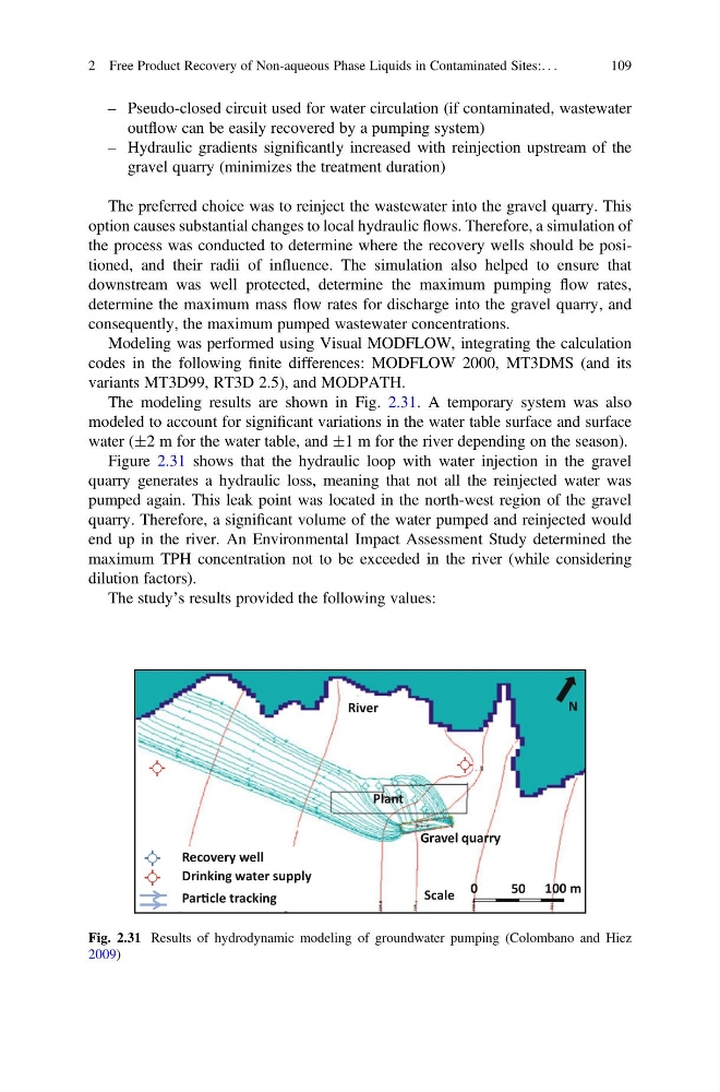
The modeling results are shown in Fig. 2.31. A temporary system was also
modeled to account for significant variations in the water table surface and surface
water (Æ2 m for the water table, and Æ1 m for the river depending on the season).
Figure 2.31 shows that the hydraulic loop with water injection in the gravel
quarry generates a hydraulic loss, meaning that not all the reinjected water was
pumped again. This leak point was located in the north-west region of the gravel
quarry. Therefore, a significant volume of the water pumped and reinjected would
end up in the river. An Environmental Impact Assessment Study determined the
maximum TPH concentration not to be exceeded in the river (while considering
dilution factors).
The study’s results provided the following values:
Scale 0
50 100 m
River
Plant
Gravel quarry
Recovery well
Drinking water supply
ParƟcle tracking
N
Fig. 2.31 Results of hydrodynamic modeling of groundwater pumping (Colombano and Hiez
2009)
2 Free Product Recovery of Non-aqueous Phase Liquids in Contaminated Sites:. . .
109
outflow can be easily recovered by a pumping system)
– Hydraulic gradients significantly increased with reinjection upstream of the
gravel quarry (minimizes the treatment duration)
The preferred choice was to reinject the wastewater into the gravel quarry. This
option causes substantial changes to local hydraulic flows. Therefore, a simulation of
the process was conducted to determine where the recovery wells should be positioned, and their radii of influence. The simulation also helped to ensure that
downstream was well protected, determine the maximum pumping flow rates,
determine the maximum mass flow rates for discharge into the gravel quarry, and
consequently, the maximum pumped wastewater concentrations.
Modeling was performed using Visual MODFLOW, integrating the calculation
codes in the following finite differences: MODFLOW 2000, MT3DMS (and its
variants MT3D99, RT3D 2.5), and MODPATH.
The modeling results are shown in Fig. 2.31. A temporary system was also
modeled to account for significant variations in the water table surface and surface
water (Æ2 m for the water table, and Æ1 m for the river depending on the season).
Figure 2.31 shows that the hydraulic loop with water injection in the gravel
quarry generates a hydraulic loss, meaning that not all the reinjected water was
pumped again. This leak point was located in the north-west region of the gravel
quarry. Therefore, a significant volume of the water pumped and reinjected would
end up in the river. An Environmental Impact Assessment Study determined the
maximum TPH concentration not to be exceeded in the river (while considering
dilution factors).
The study’s results provided the following values:
Scale 0
50 100 m
River
Plant
Gravel quarry
Recovery well
Drinking water supply
ParƟcle tracking
N
Fig. 2.31 Results of hydrodynamic modeling of groundwater pumping (Colombano and Hiez
2009)
2 Free Product Recovery of Non-aqueous Phase Liquids in Contaminated Sites:. . .
109